-
Featured User: kurt

Open-source hardware project hosting is my passion. I spend most of my free time building neat gadgets or planning what I'll build next. I love building things, and I want to make Open Hardware Hub a place that inspires others to build, ...
-
Updates 2013 February 18
It's been a while, hasn't it? Well, that's ok because we've got a lot of updates to talk about. Most of these have been effective on the site fora couple weeks now. A few may or may not be active when this article gets posted, but they'll certainly be applied in the ...
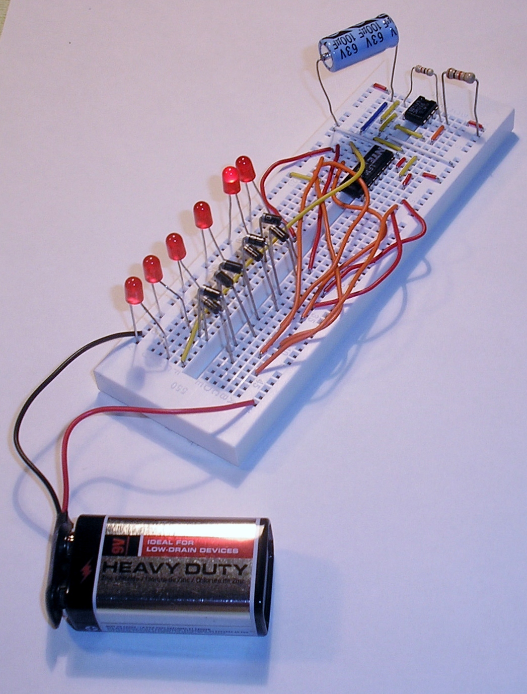
Knight Rider Lights

Files
- Knight_Rider_Lights.sch - Knight Rider Lights EAGLE Schematic
- Knight_Rider_Lights_Schematic.pdf - Knight Rider Lights PDF Schematic
Bill of Materials
| Qty | Part # | Description | Schematic ID | Source | |
|---|---|---|---|---|---|
| 2 |
|
CF14JT1K00 | 1/4w 1K ohms 5% Carbon Film Resistors | R1,R2 | Source |
| 1 |
|
SK101M016ST | Capacitor | C1 | Source |
| 1 |
|
NE555P | TIMER SINGLE PRECISION,DIP8 ,0.5MHZ | IC1 | Source |
| 1 |
|
CD4017BE | IC, 4000 CMOS, 4017, DIP16, 18V | IC2 | Source |
| 8 |
|
1N4001-G | DIODE RECTIFIER 1A 50V DO-41 | D1,D2,D3,D4,D5,D6,D7,D8 | Source |
| 6 |
|
WP7104ID | Red T-1 3 mm 40° Tinted Diffused 20 mcd 2 V Solid State LED Lamp Through Hole | LED1,LED2,LED3,LED4,LED5,LED6 | Source |
| 1 |
|
BS6I | SNAPS 9V 6" LEADS I-STYLE | JP1 | Source |
Download BOM w/o images
Download BOM w/ images
Steps
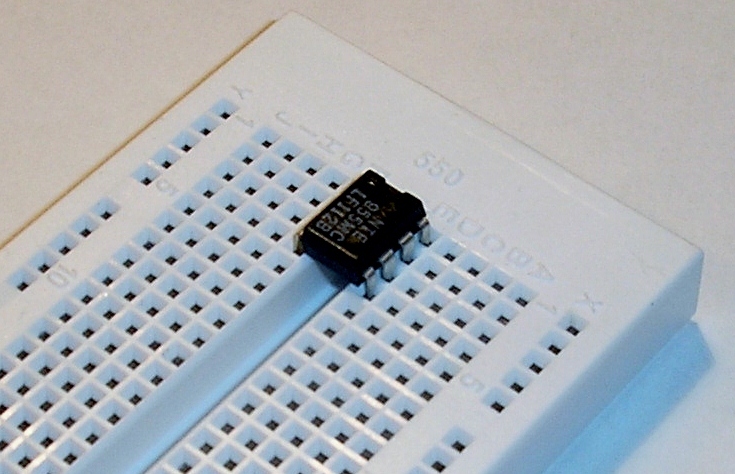
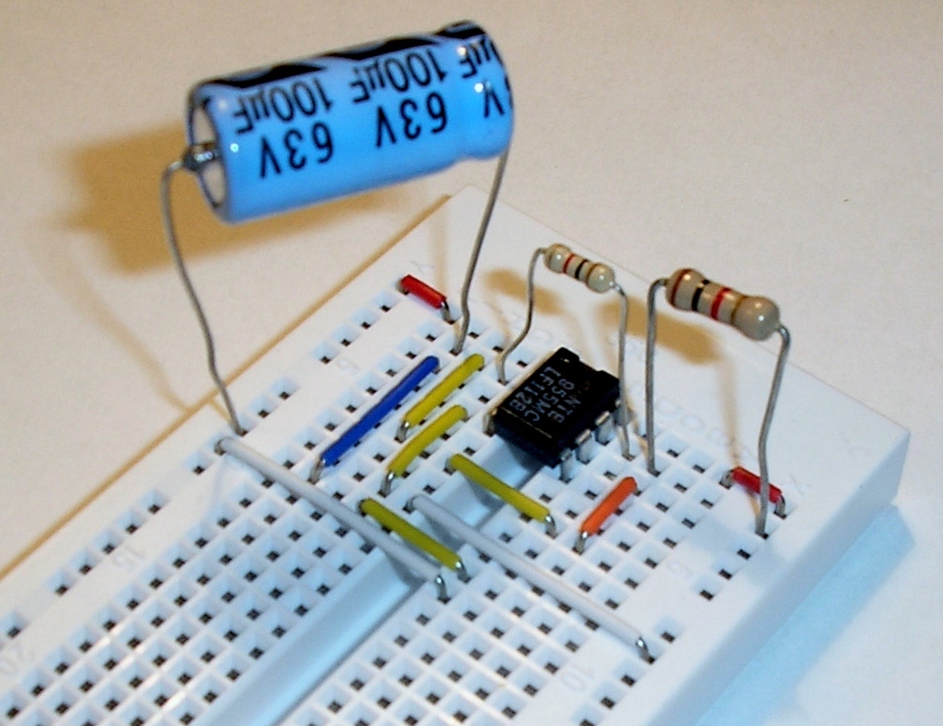
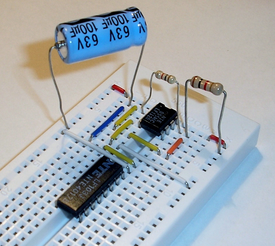
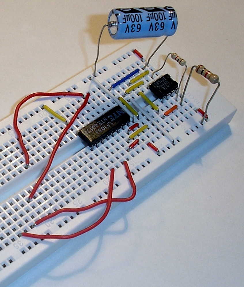
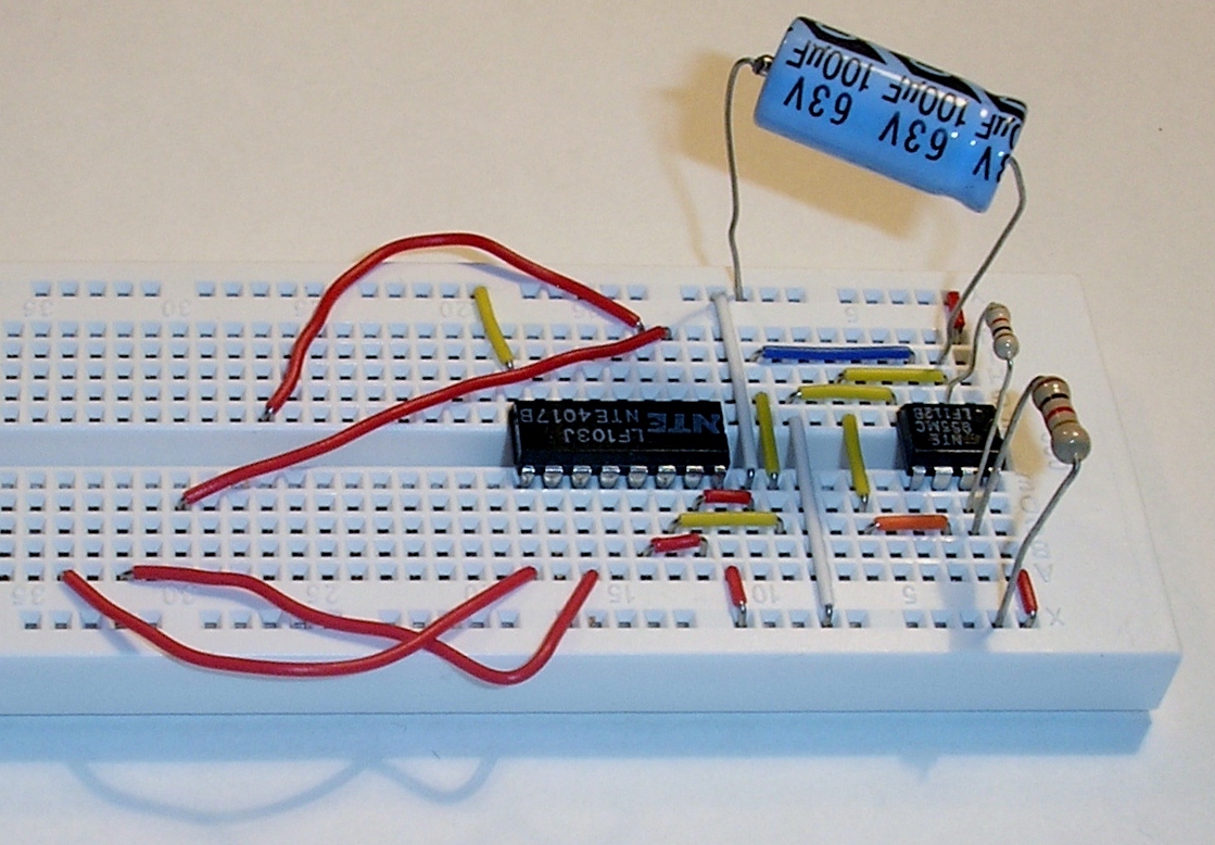
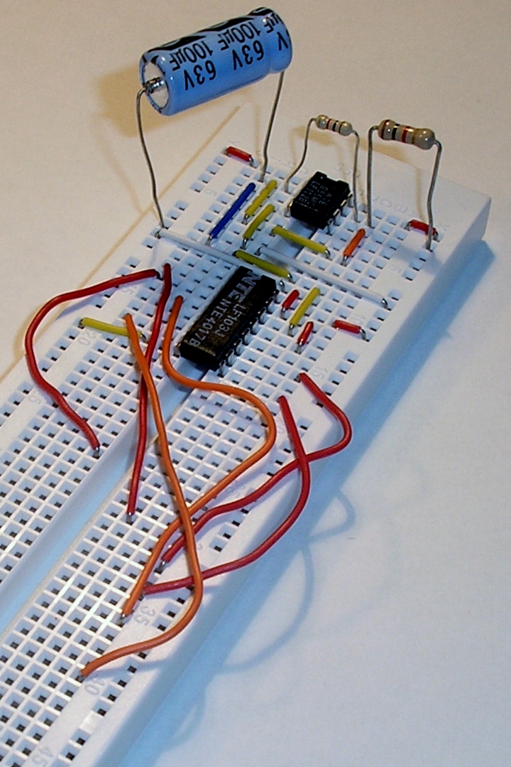
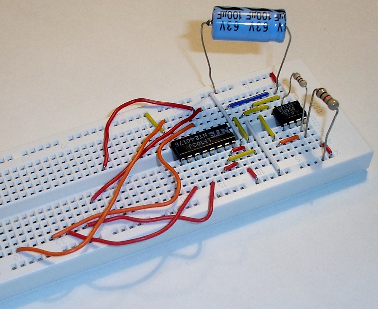
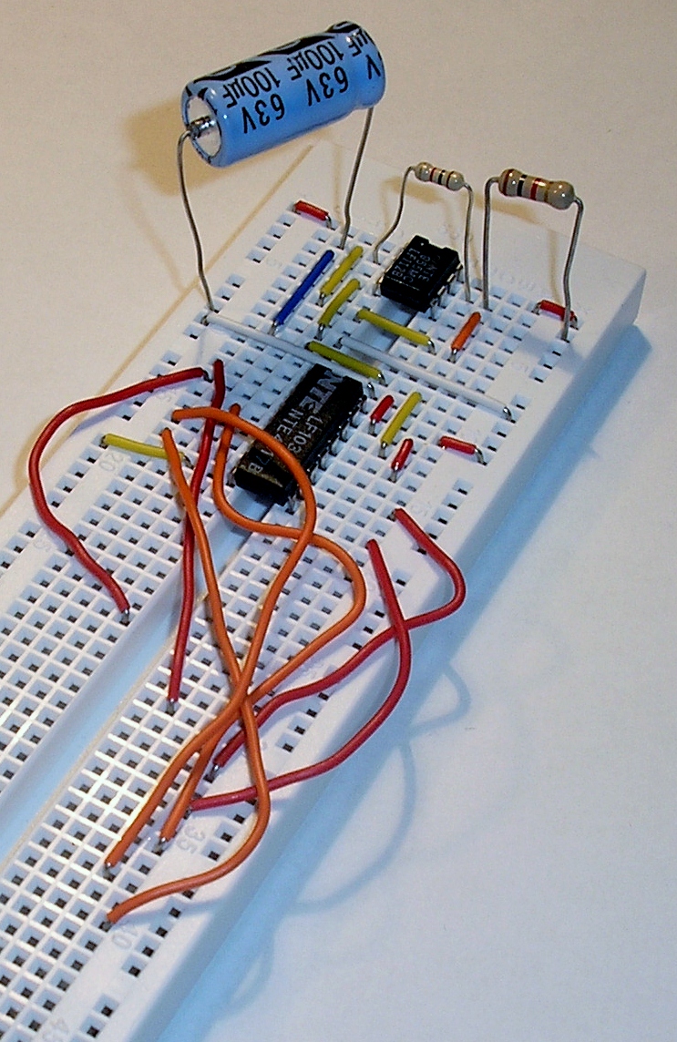
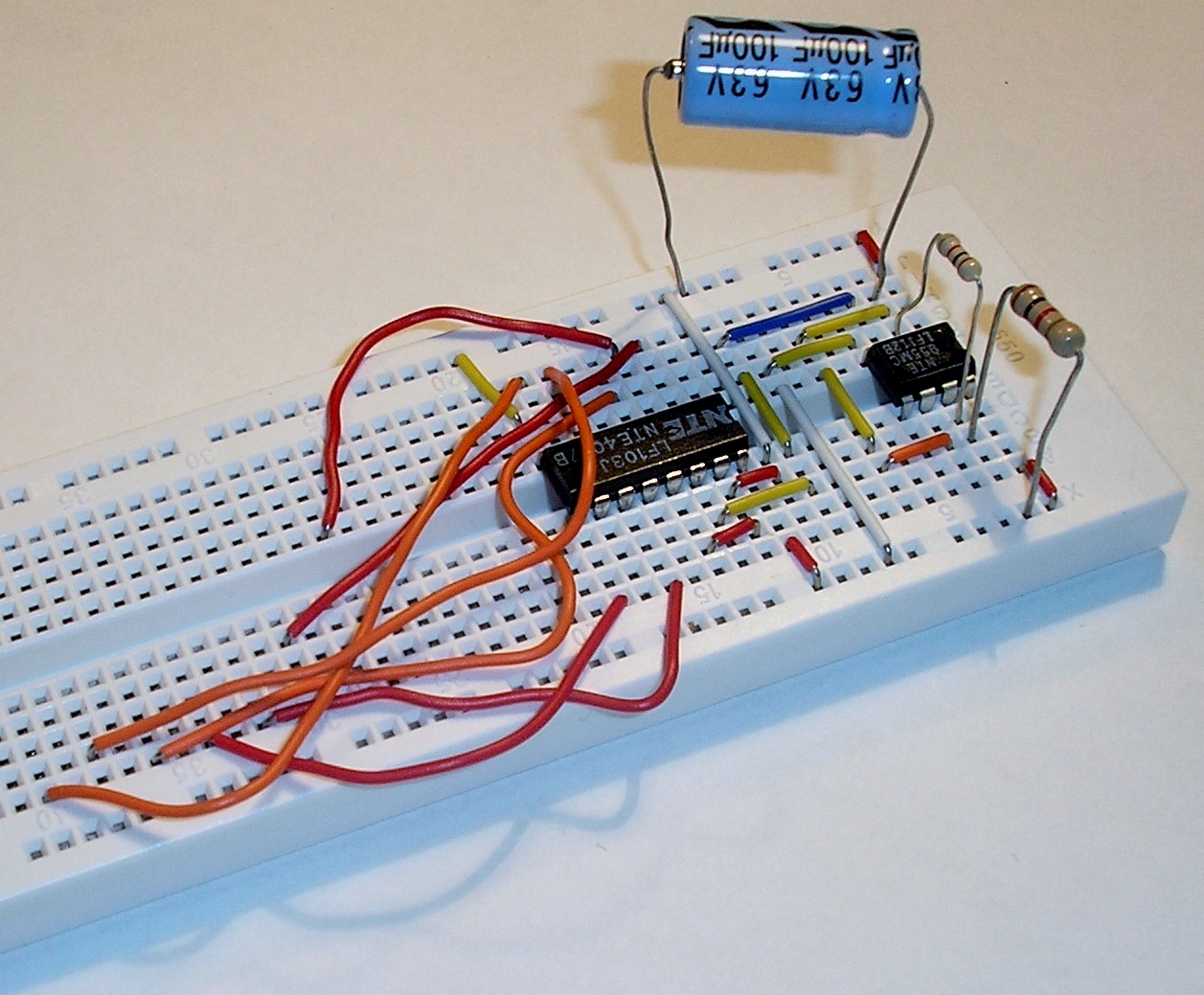
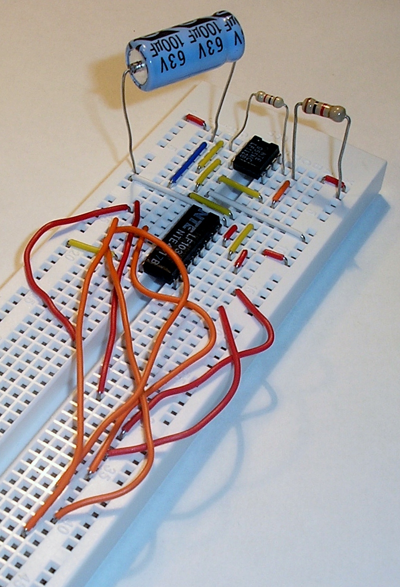
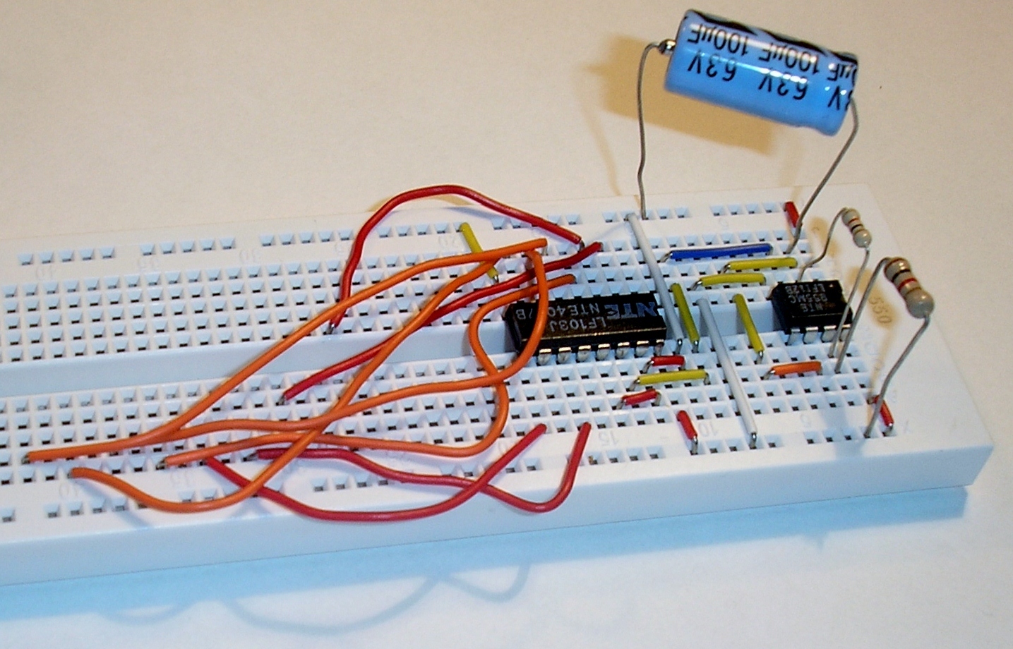
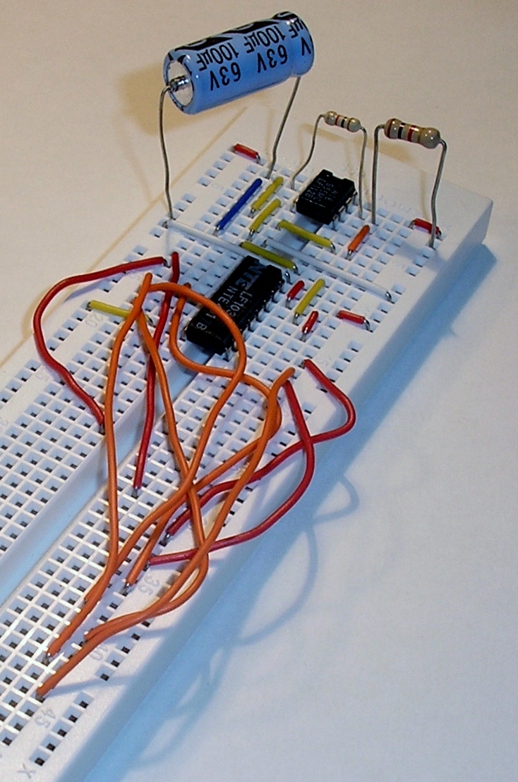
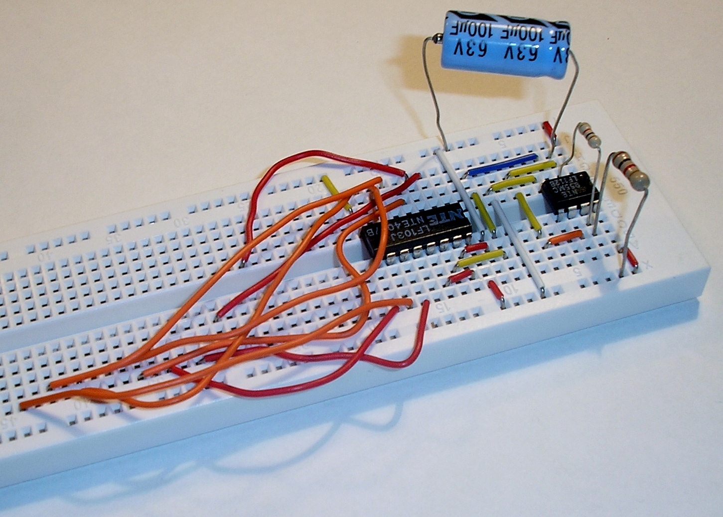
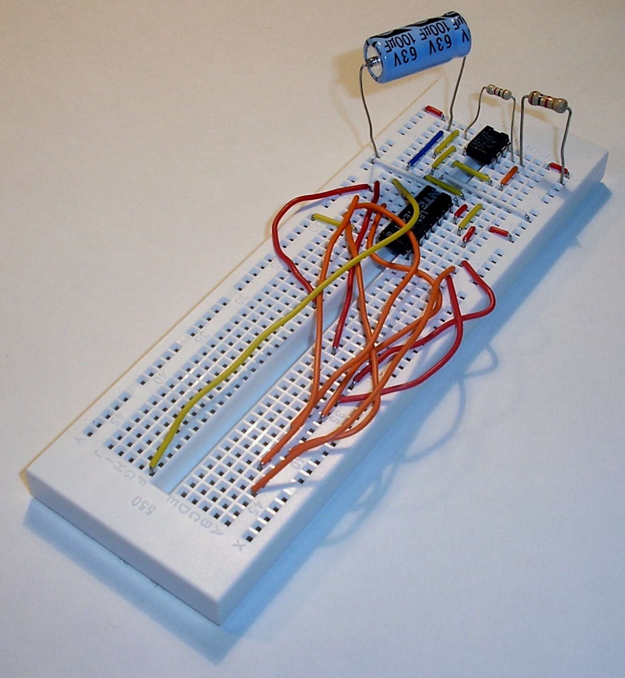
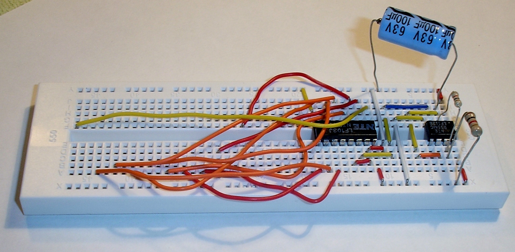
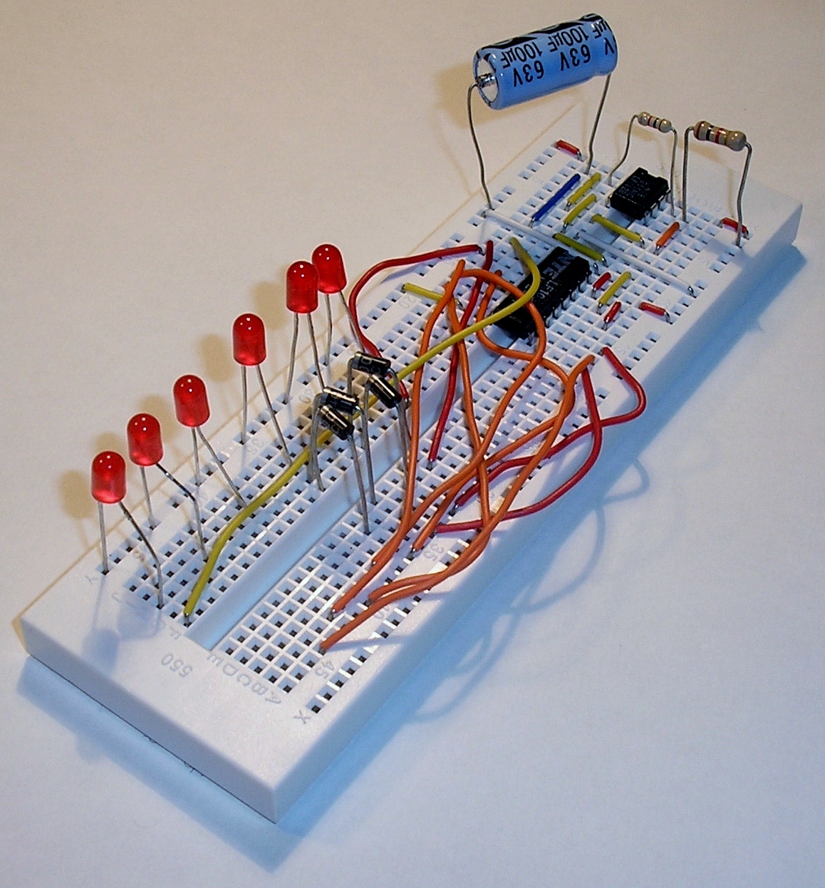
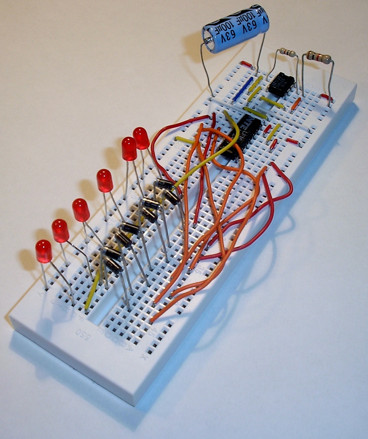
1. Insert 555 timer
Insert the 555 timer at the top of the breadboard. Make sure that the dimple on the top surface of the package is towards the top of the bread board.
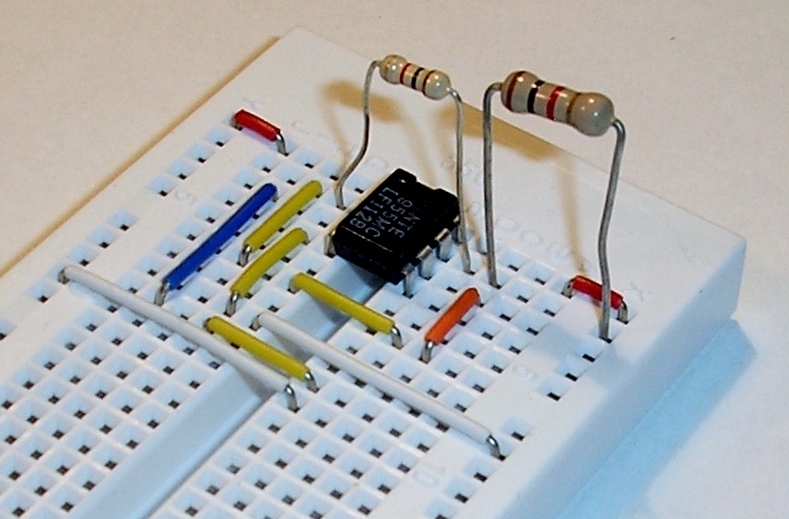
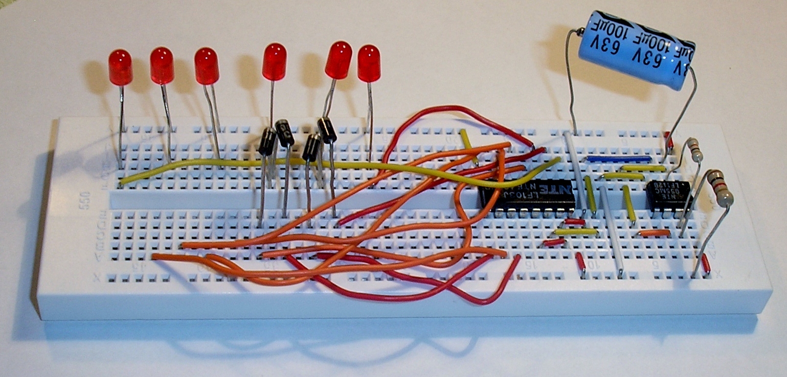
3. Insert resistors
Insert two 1k resistors as shown. The first one is between pins 2 and 7 of the 555 timer, and the second one is between pin 7 and +9V.
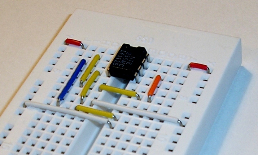
4. Insert capacitor
Insert the 100uF capacitor as shown. The negative leg should be plugged into the ground rail on the left side of the bread board. The negative leg is indicated by a stripe or arrows on the cylinder.
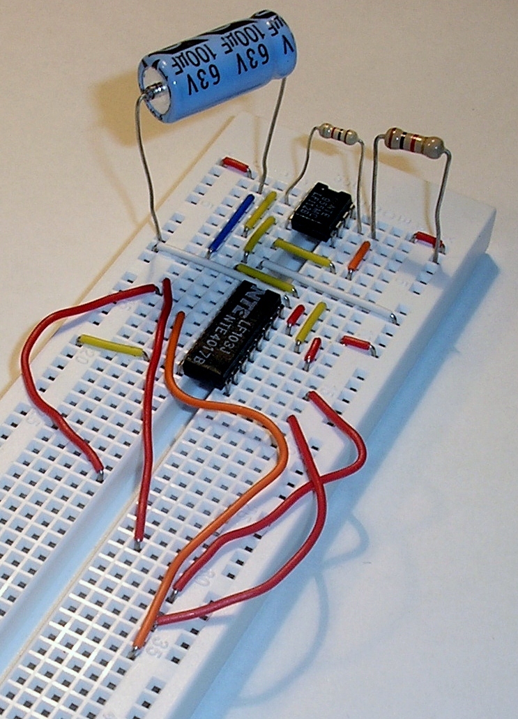
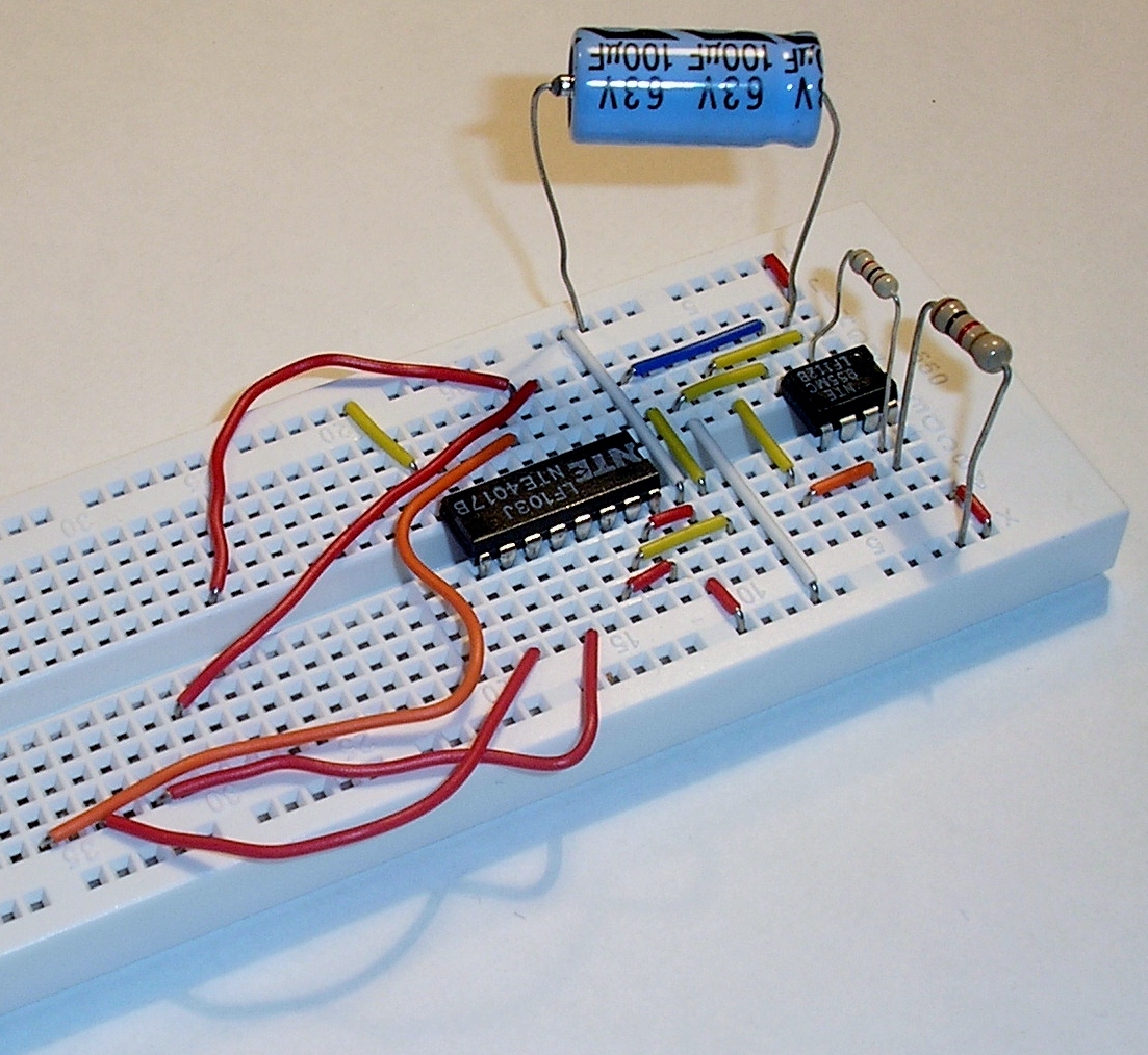
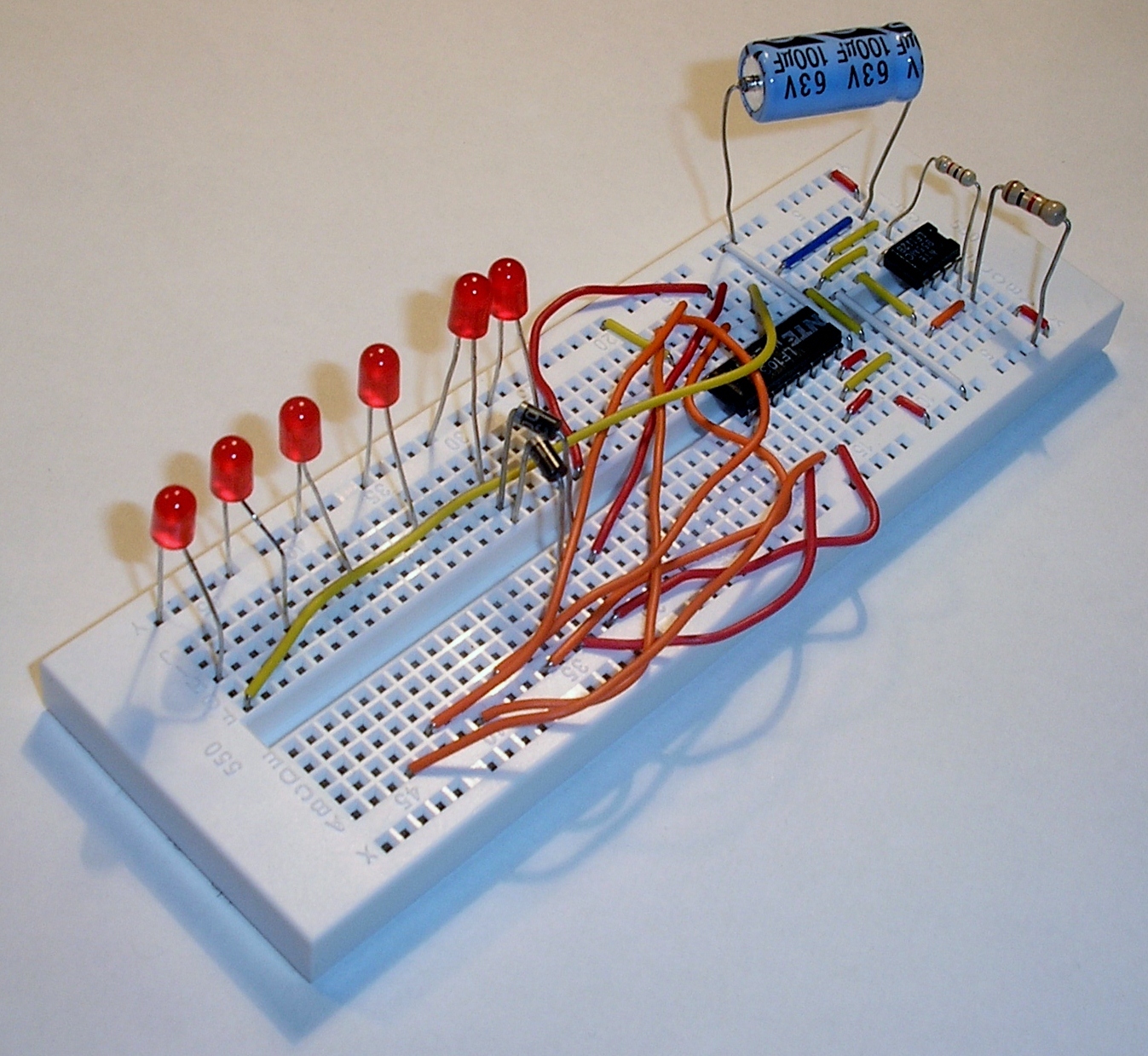
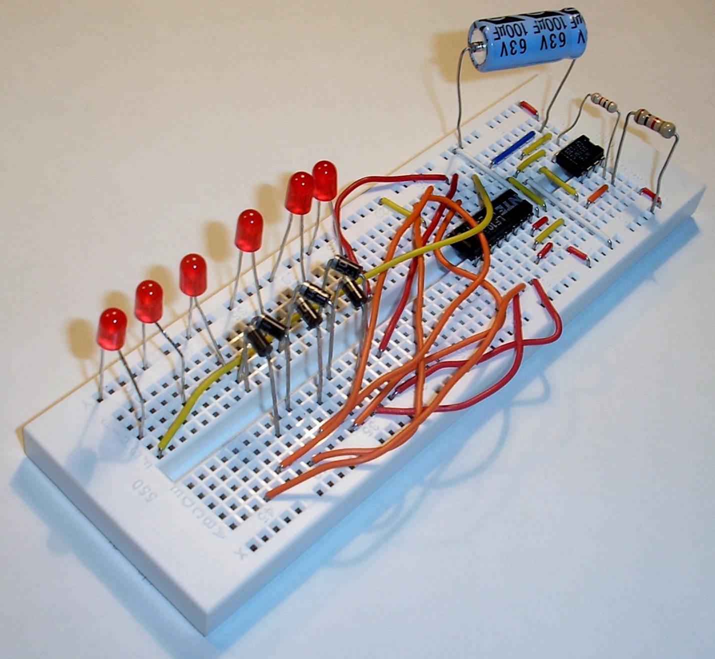
14. Insert LEDs
Insert the LEDs as shown. The short legs of the LEDs plug in to the ground rail on the left side of the bread board.
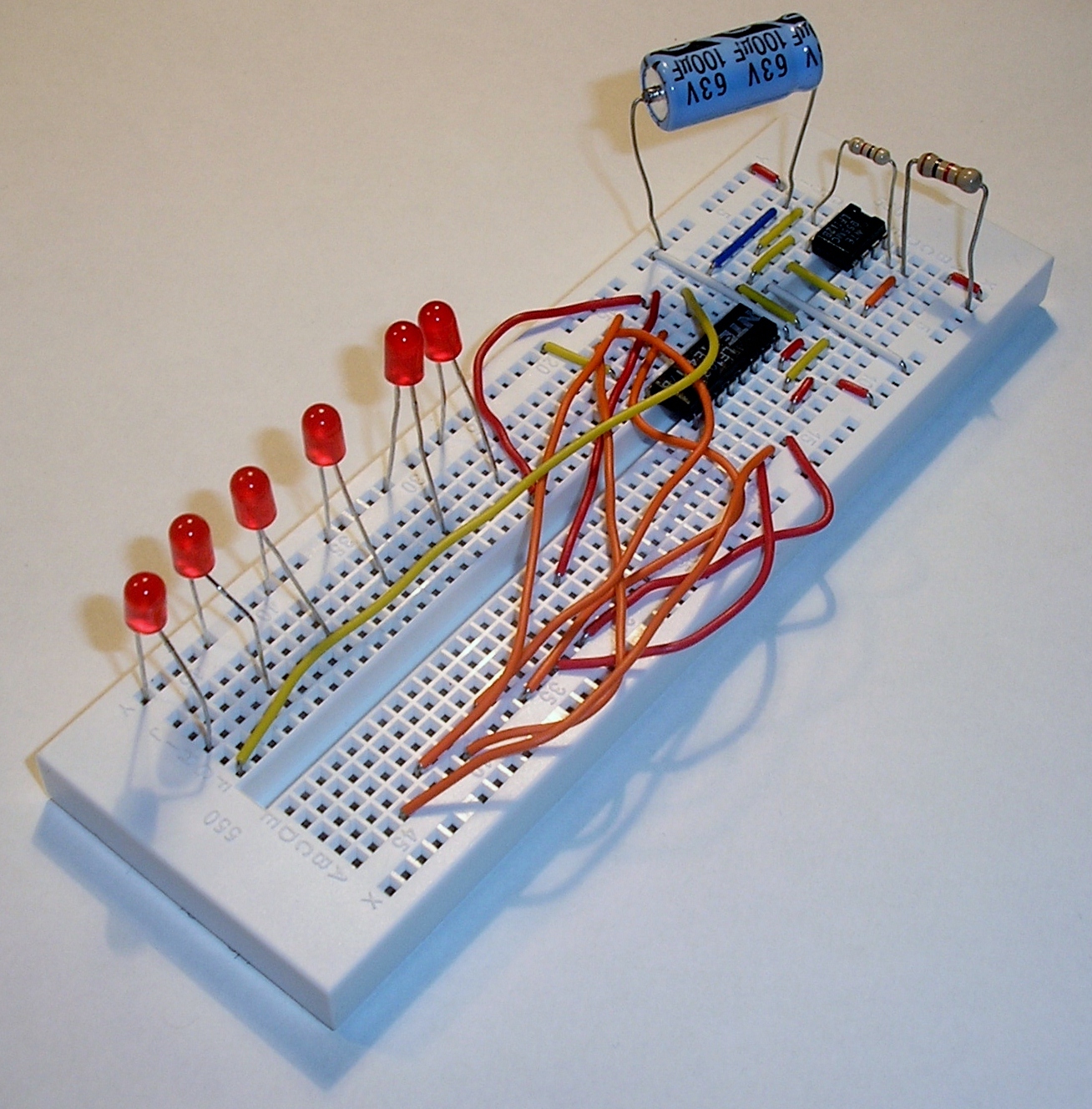
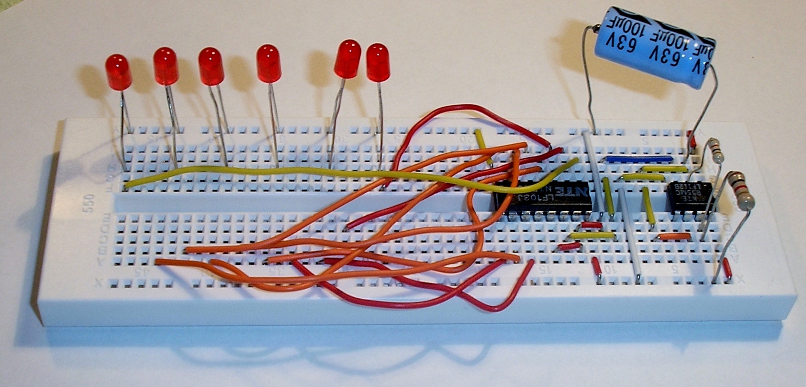
15. Insert diodes
Insert a pair of 1N4001 diodes as shown. These diodes connect to the second LED from the top. Take note of the orientation of the white stripe on the body of the diodes. The polarity (which way the diode is plugged in) does matter.
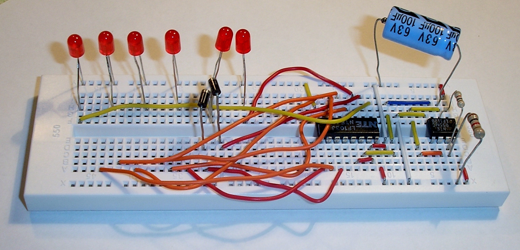
16. Insert diodes
Insert a pair of 1N4001 diodes as shown. These diodes connect to the third LED from the top.
17. Insert diodes
Insert a pair of 1N4001 diodes as shown. These diodes connect to the fourth LED from the top.
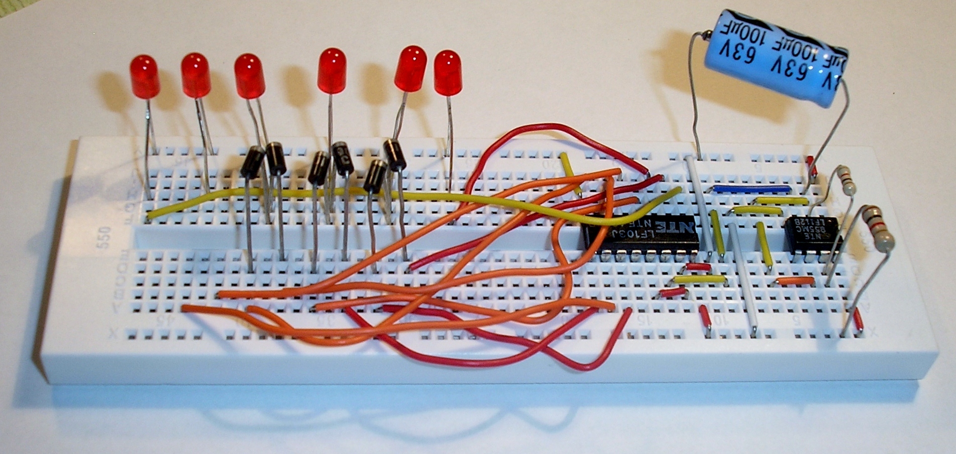
18. Insert diodes
Insert a pair of 1N4001 diodes as shown. These diodes connect to the fifth LED from the top.
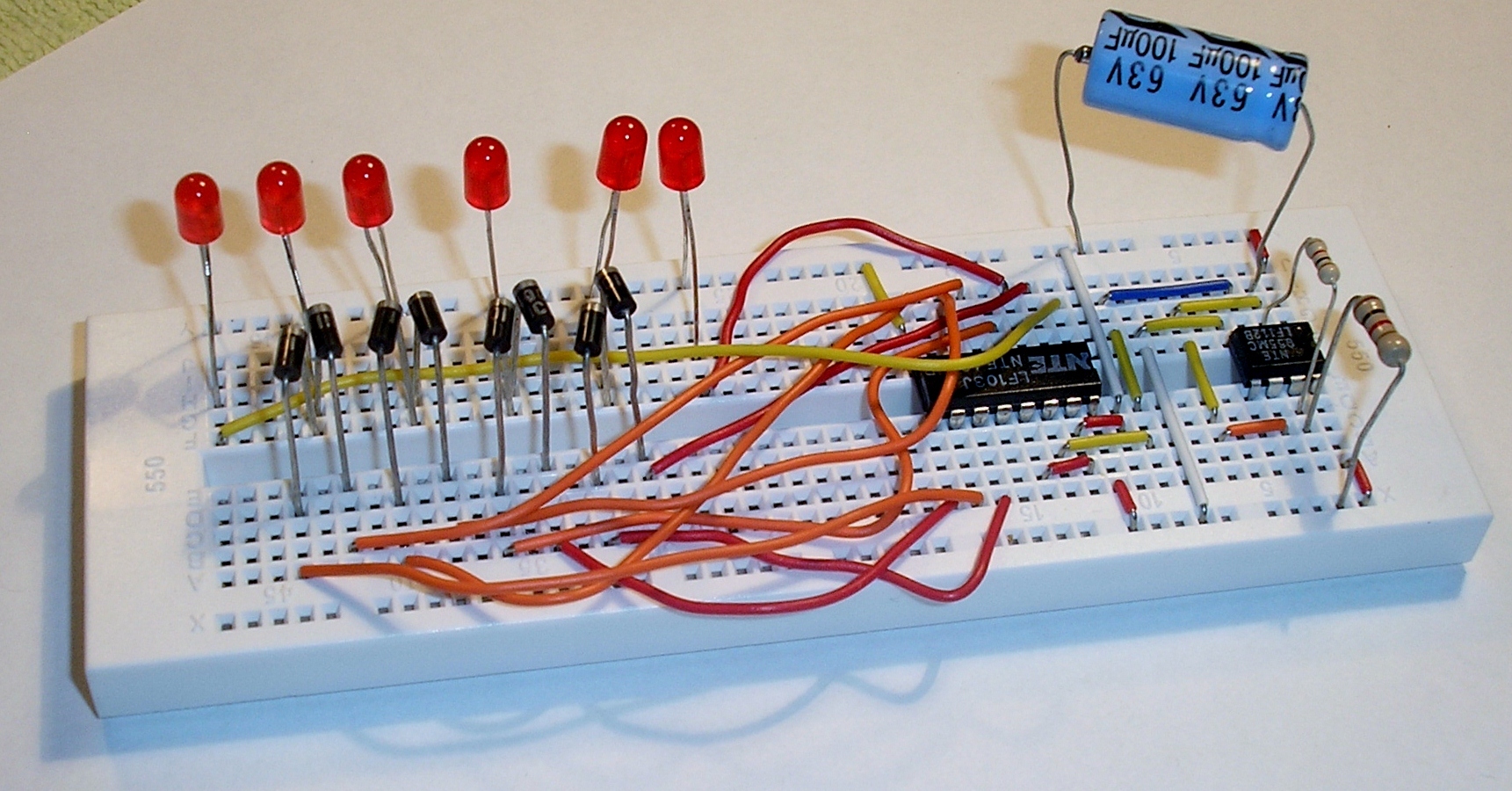
19. Connect 9V Battery
Connect a 9V battery as shown. The red wire is +9V, and the black wire is ground. Watch the LEDs light up in sequence and "bounce" back and forth.

Download steps w/o images
Download steps w/ images
Revisions
6 - updated description
5 - updated steps.
4 - changed LED part
3 - add project image descriptions
2 - added file descriptions
1 - Initial project release
Add revision
blog comments powered by Disqus
Back


