-
Featured User: kurt

Open-source hardware project hosting is my passion. I spend most of my free time building neat gadgets or planning what I'll build next. I love building things, and I want to make Open Hardware Hub a place that inspires others to build, ...
-
Updates 2013 February 18
It's been a while, hasn't it? Well, that's ok because we've got a lot of updates to talk about. Most of these have been effective on the site fora couple weeks now. A few may or may not be active when this article gets posted, but they'll certainly be applied in the ...
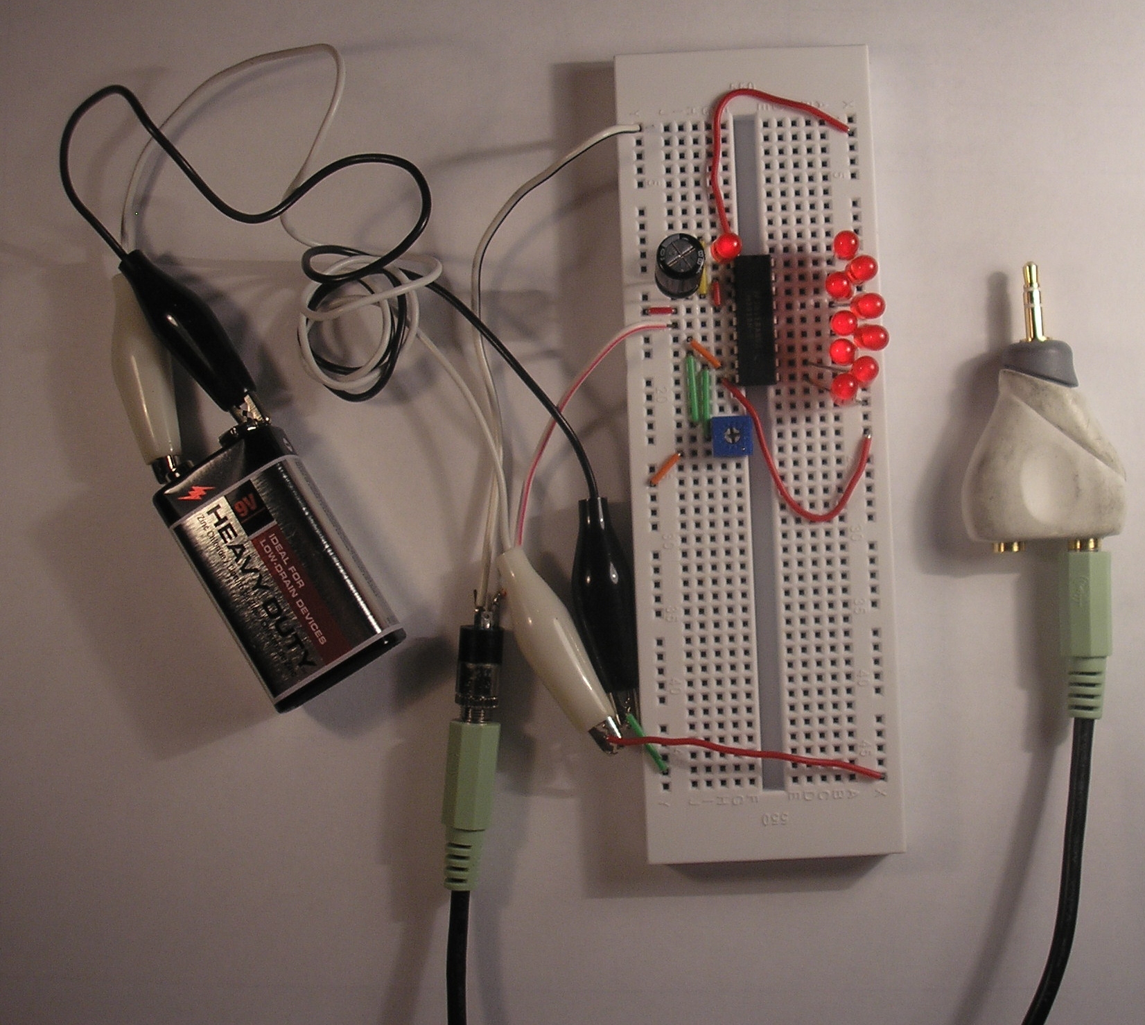
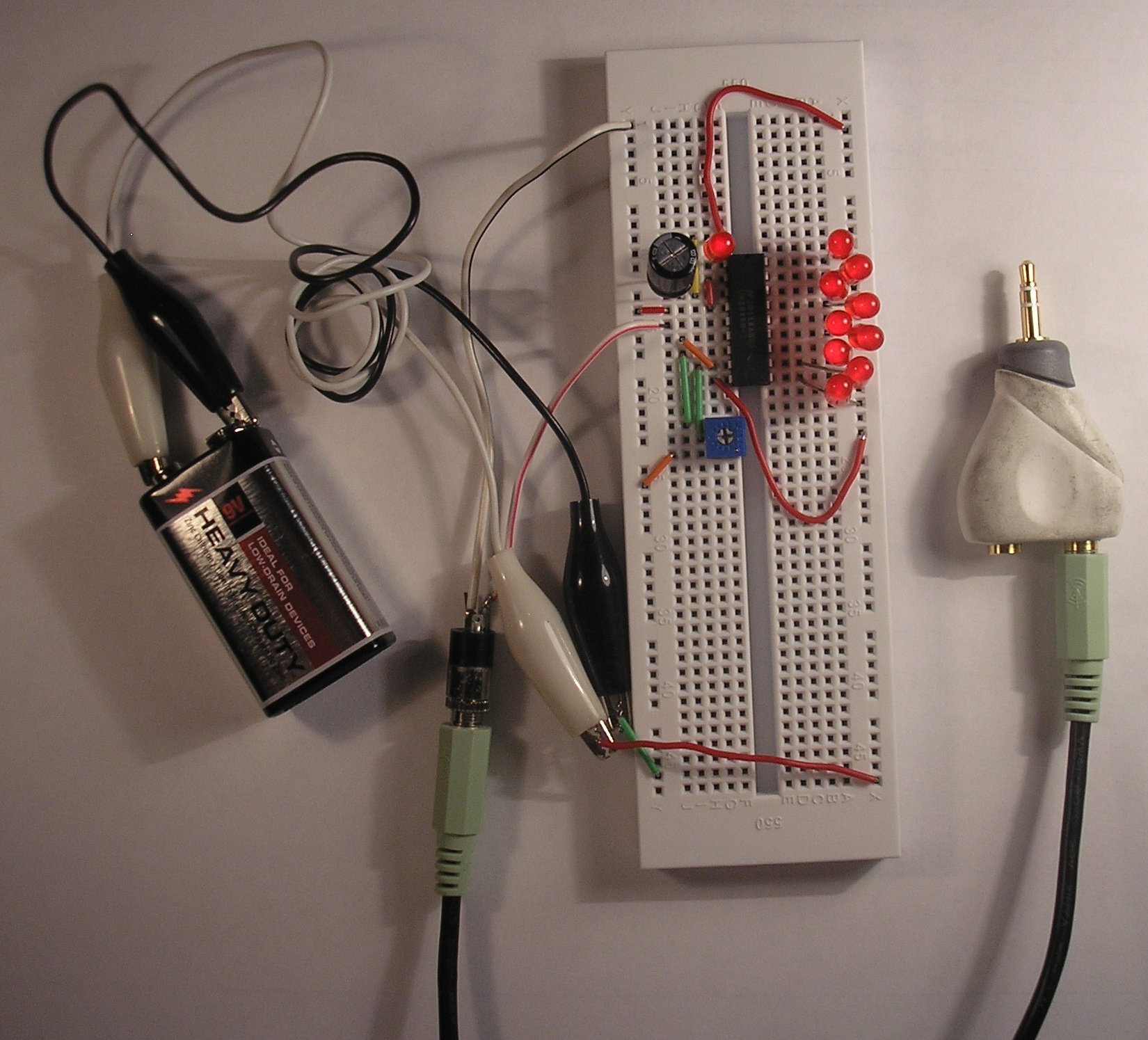
Mono VU Meter

Files
- VU Meter.sch - VU Meter EAGLE Schematic
- VU Meter Schematic.pdf - VU Meter PDF Schematic
Bill of Materials
| Qty | Part # | Description | Schematic ID | Source | |
|---|---|---|---|---|---|
| 1 |
|
SJ1-3523N | CONN JACK STEREO R/A 3PIN 3.5MM | J1 | Source |
| 1 |
|
BS6I | SNAPS 9V 6" LEADS I-STYLE | JP1 | Source |
| 1 |
|
50-0015-00 | SWITCH PB SPST ALT ACT PC MOUNT | S1 | Source |
| 1 |
|
SK100M035ST | CAPACITOR ALUM ELEC 10UF, 35V, RADIAL | C1 | Source |
| 1 |
|
EVN-D8AA03B14 | TRIMMER 10K OHM 0.1W TH | P1 | Source |
| 1 |
|
LM3916N-1 | LED BAR GRAPH DRIVER, 3916, DIP18 | IC1 | Source |
| 10 |
|
WP7113LID | 5MM LOW CURRENT RED LED, LAMP THOLE, BULK | LED1, LED2, LED3, LED4, LED5, LED6, LED7, LED8, LED9, LED10 | Source |
| 1 |
|
6LR61XWA/1SB | BATTERY IND ALKALINE 9 VOLT | Source | |
| 1 |
|
Y-Audio Cable | 6inch 3.5mm Stereo Jack/Two 3.5mm Stereo Plug Cable | Source |
Download BOM w/o images
Download BOM w/ images
Steps
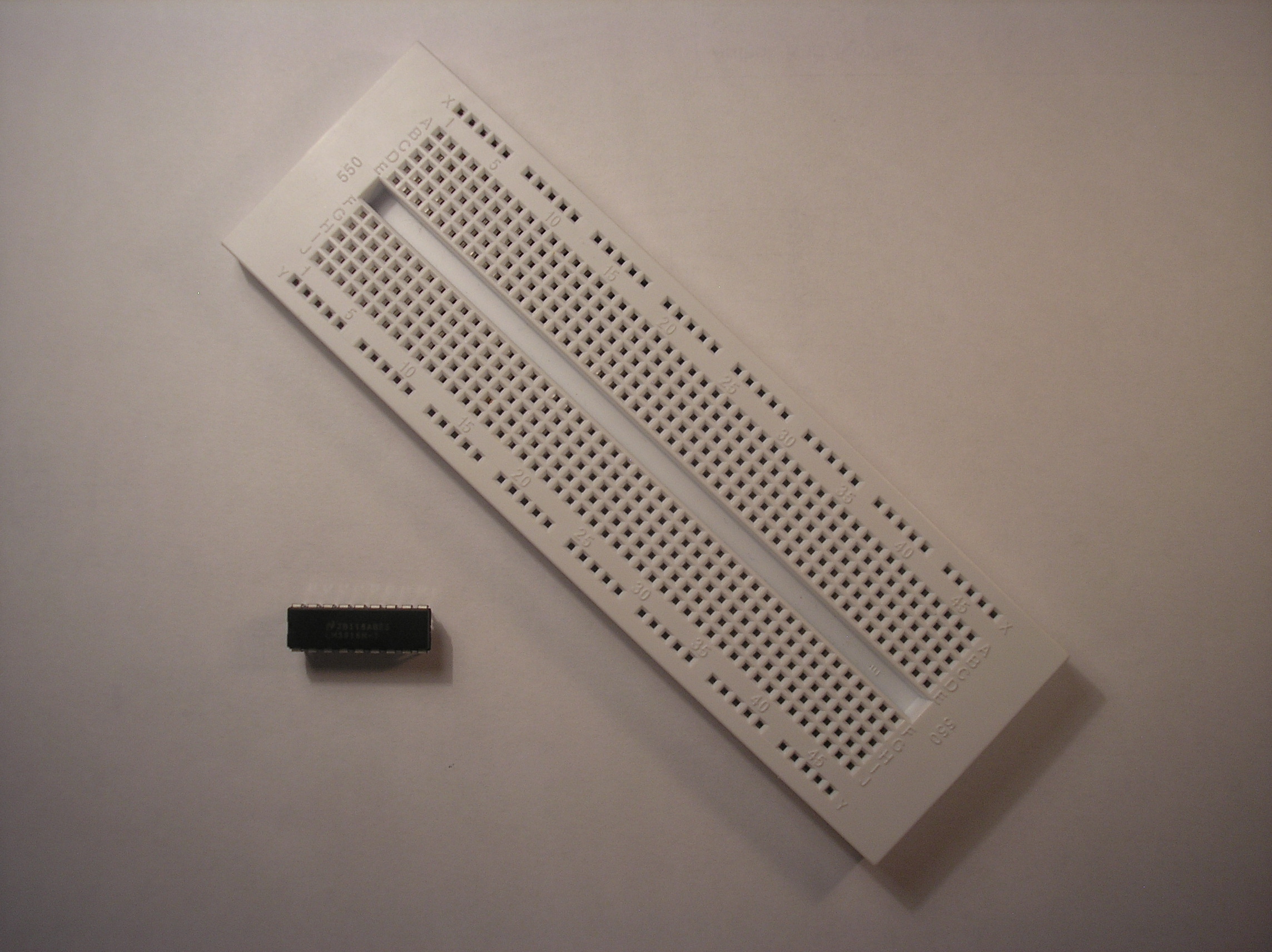
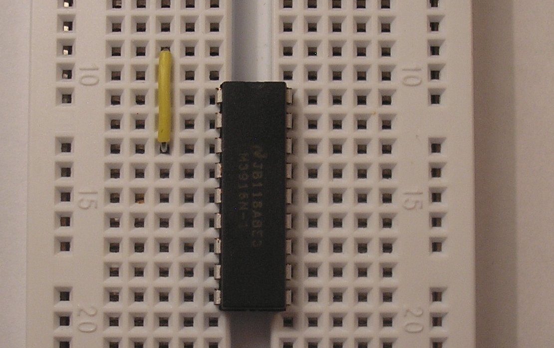
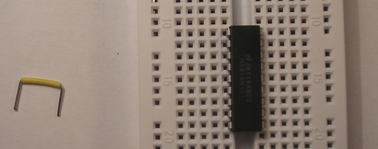
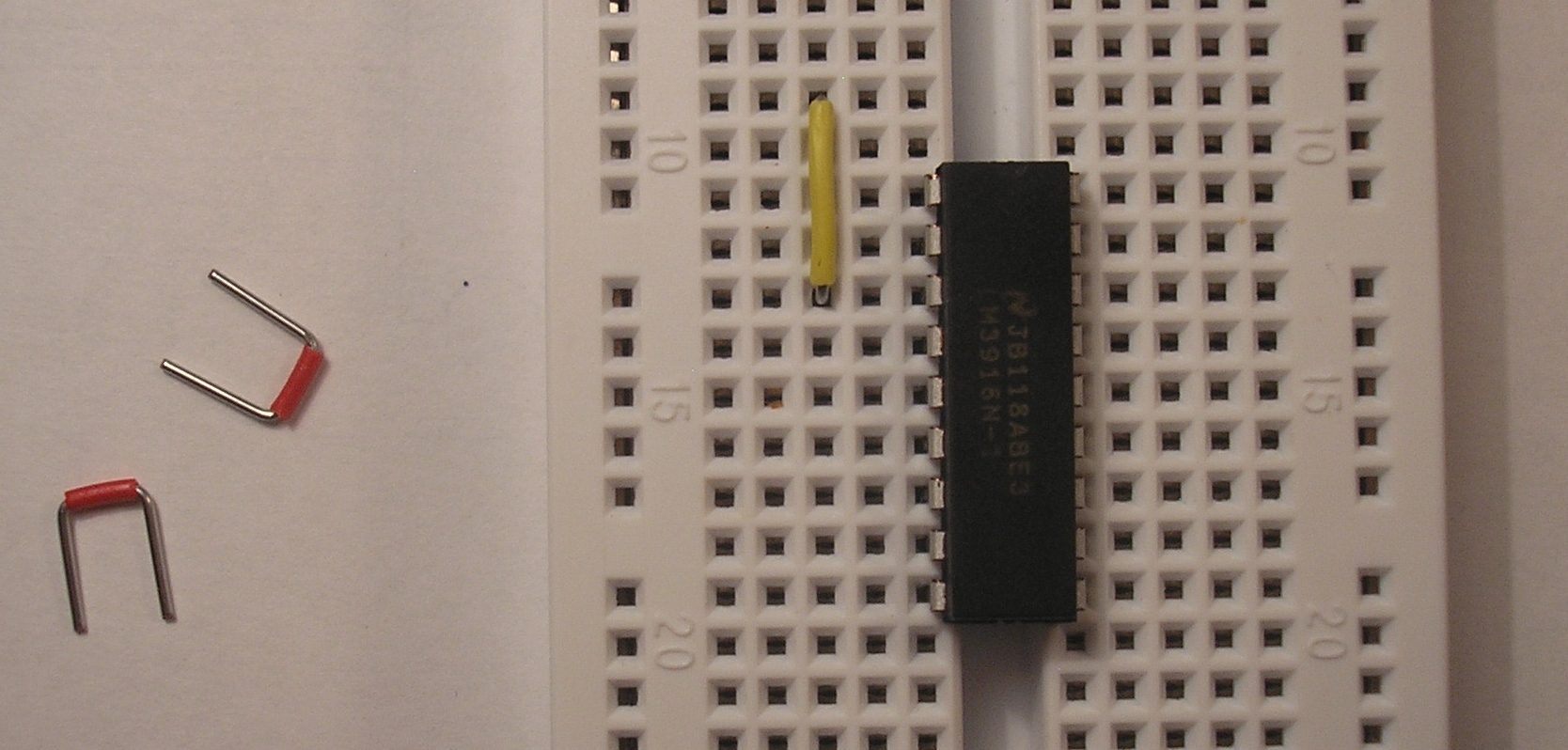
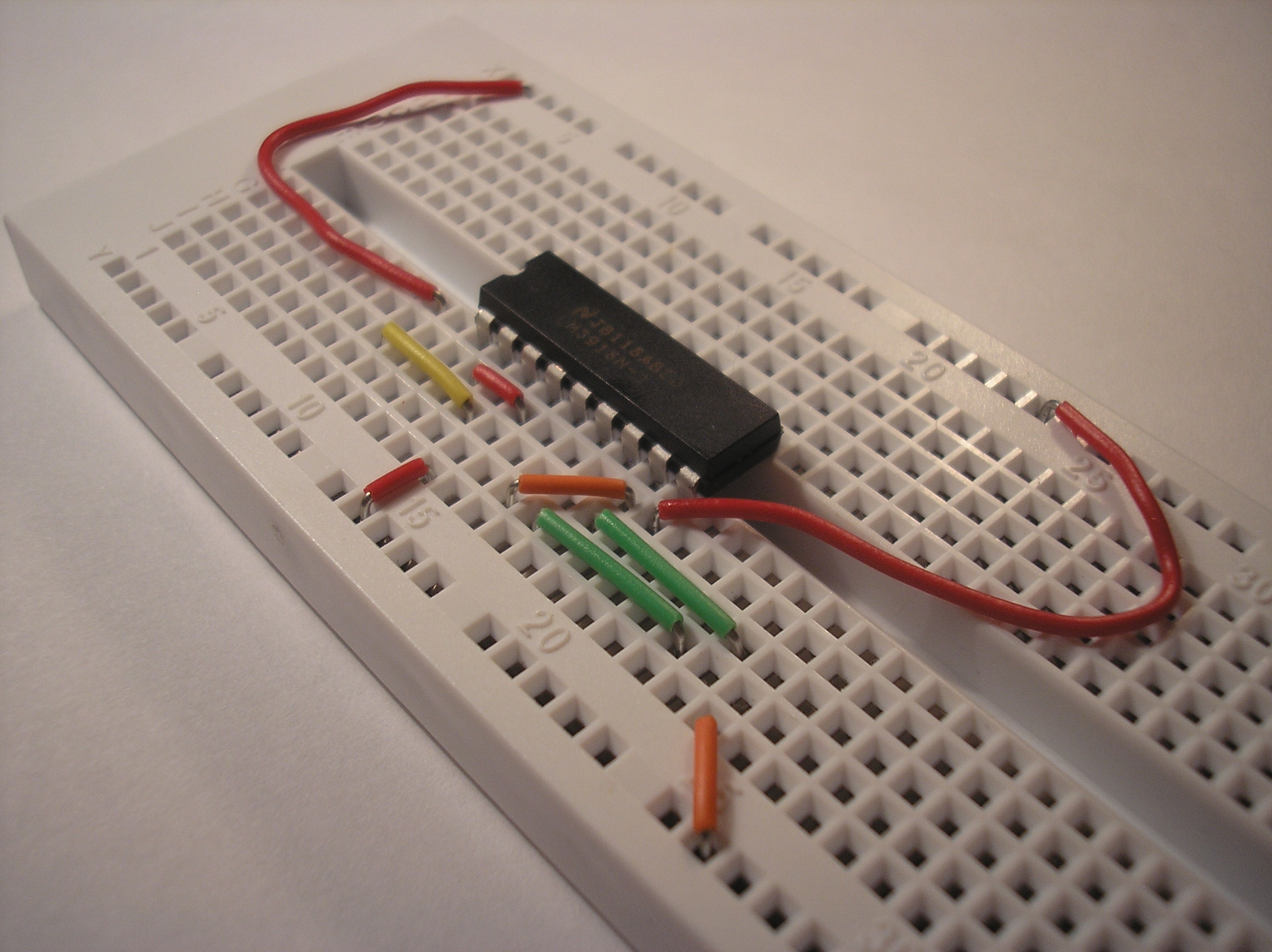
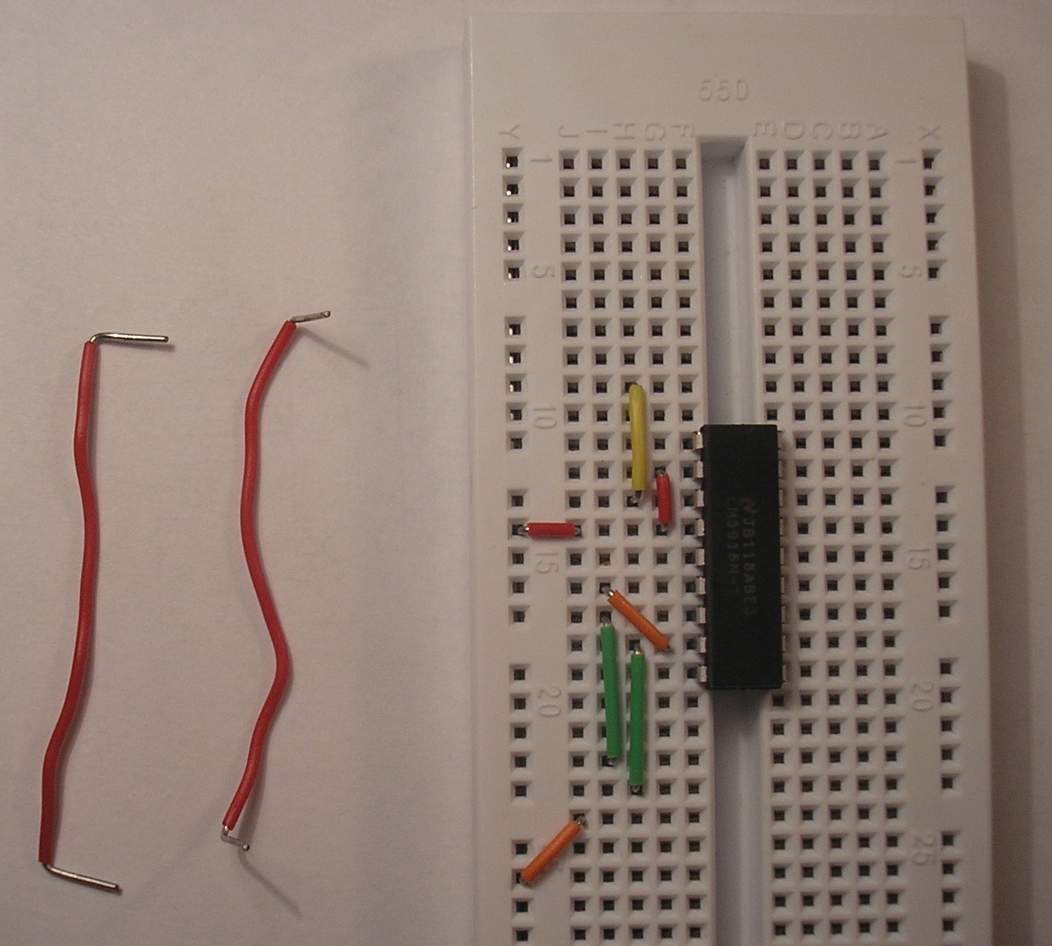
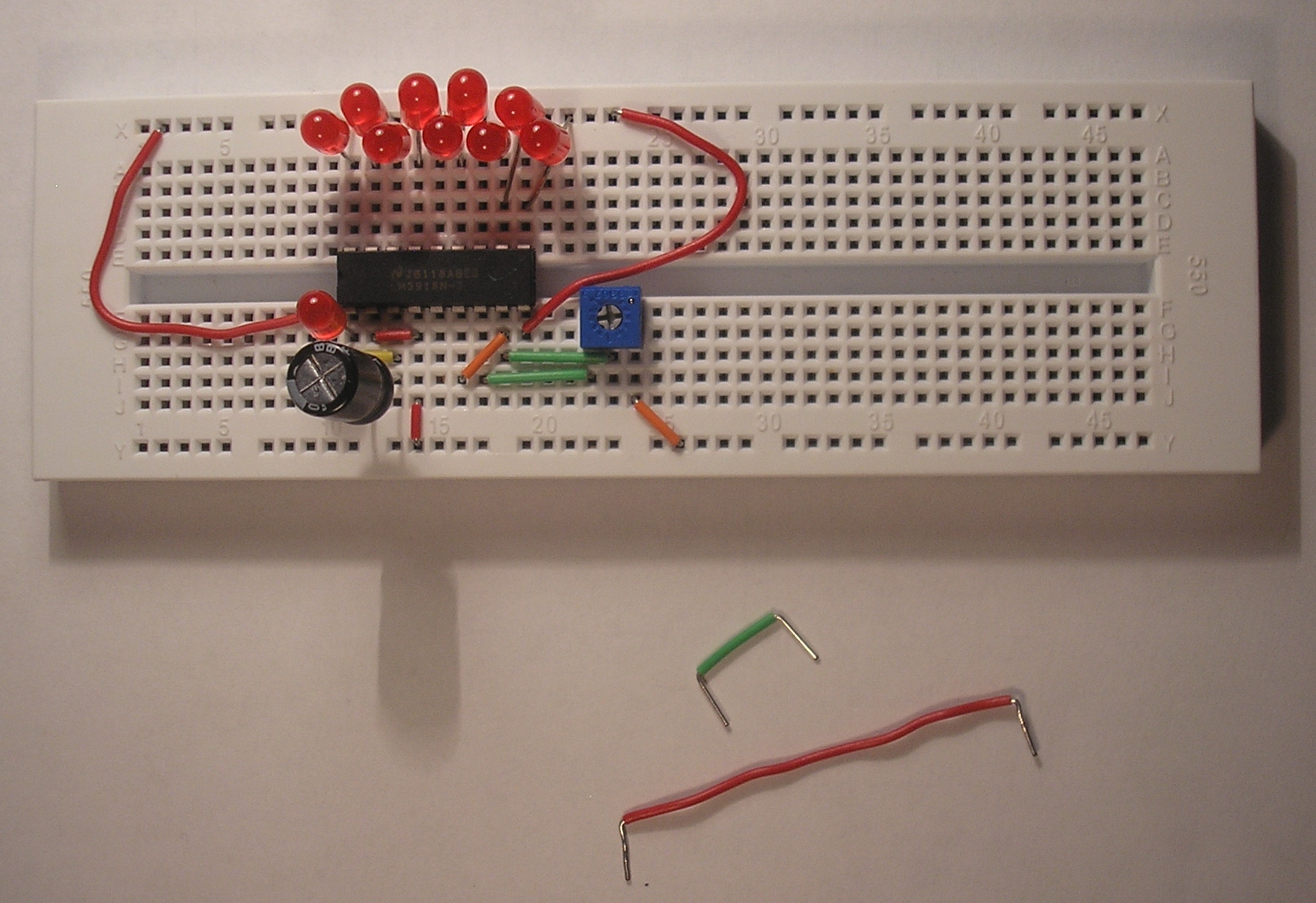
1. Get ready
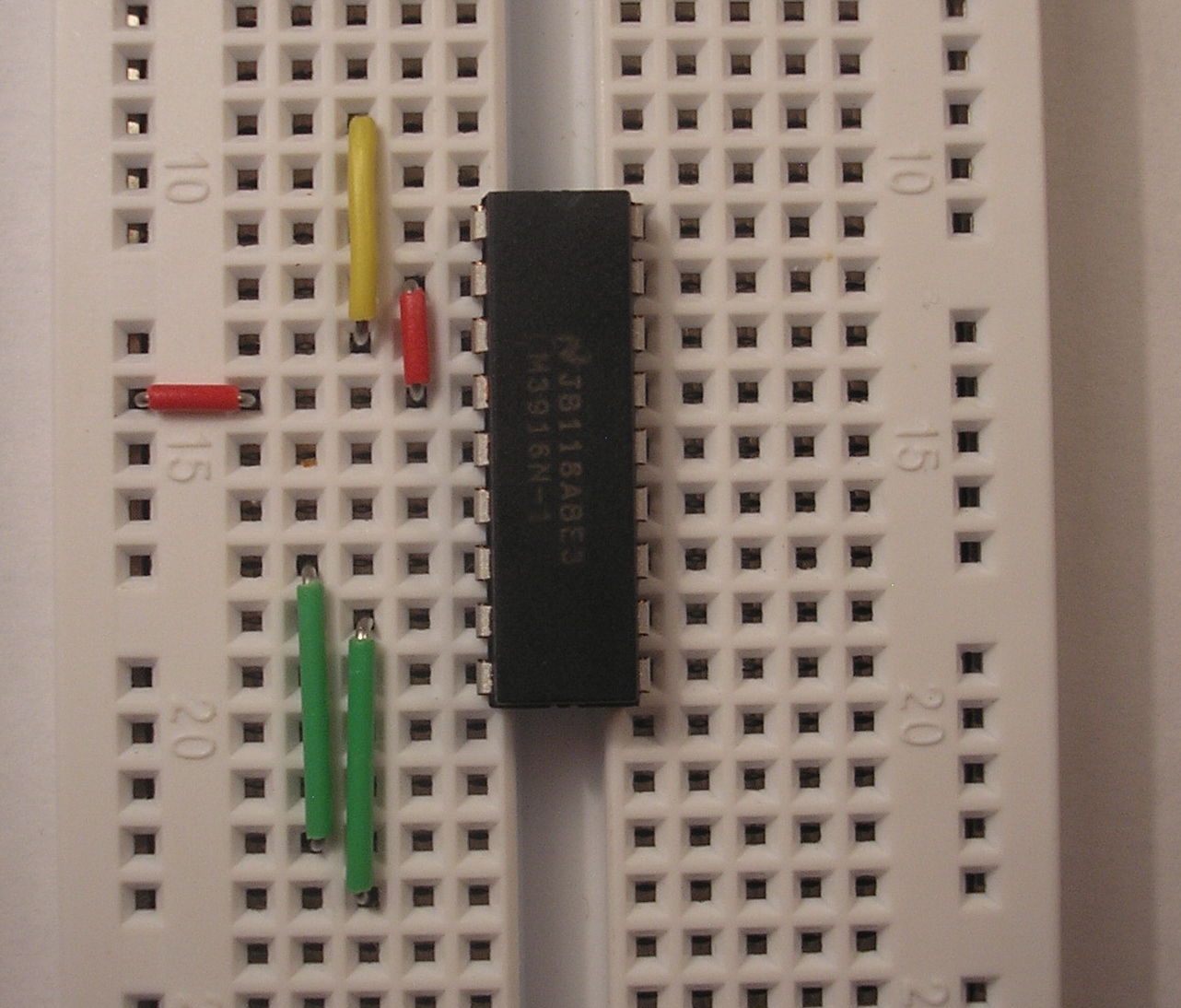
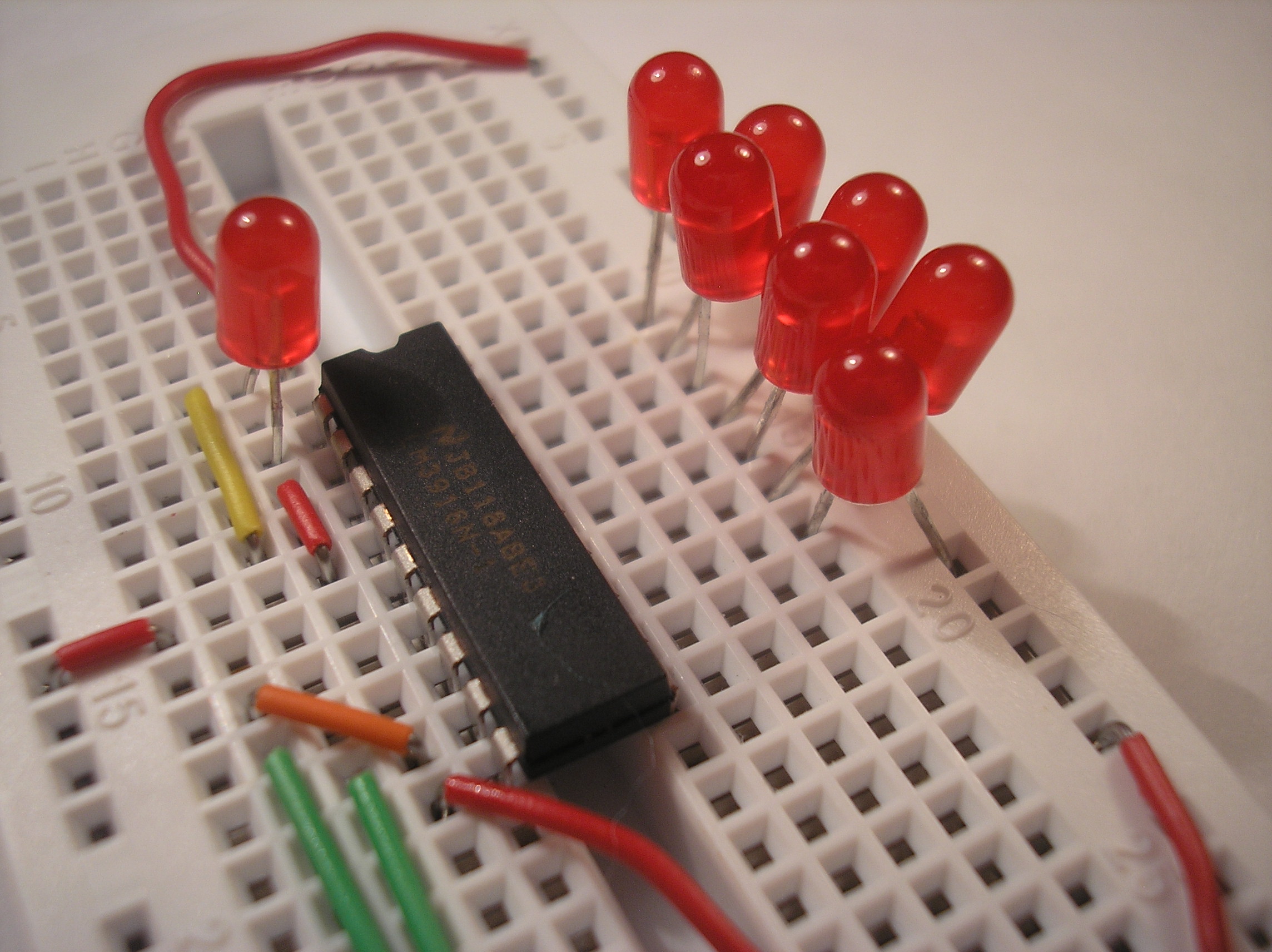
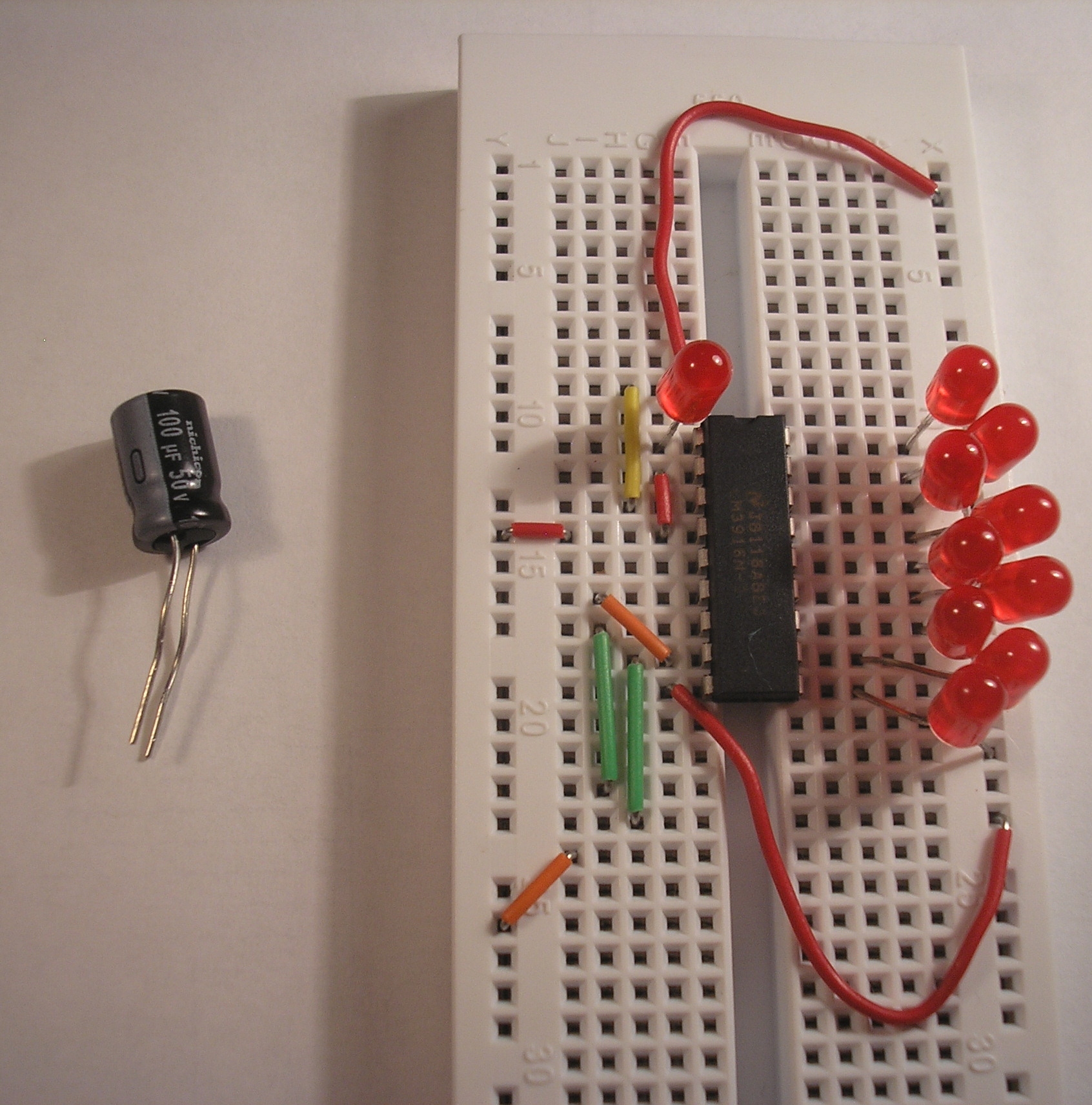
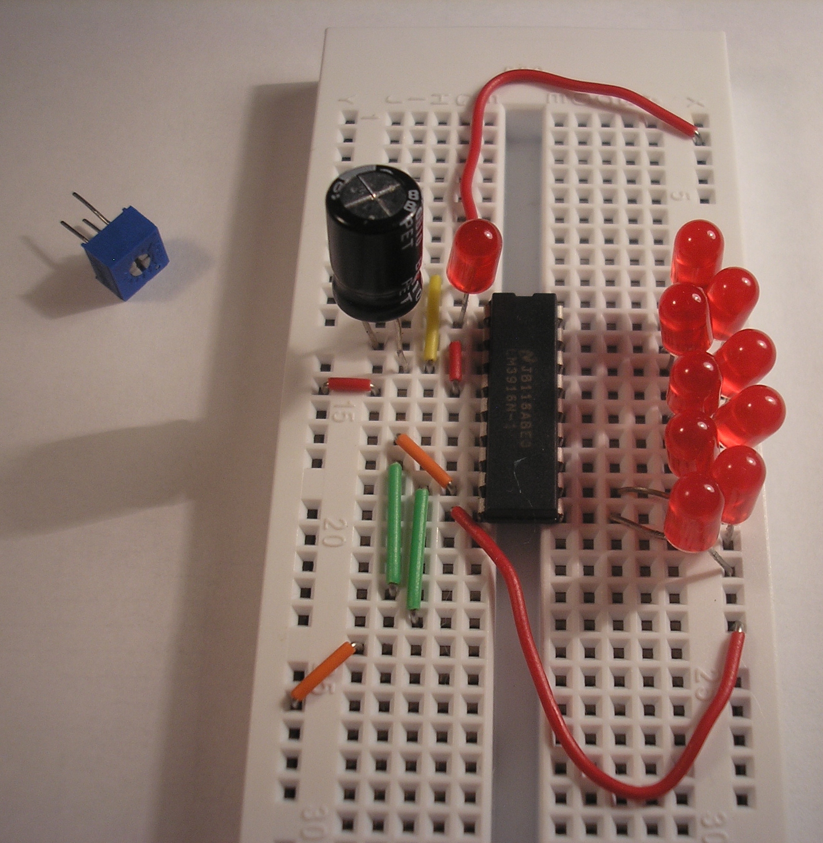
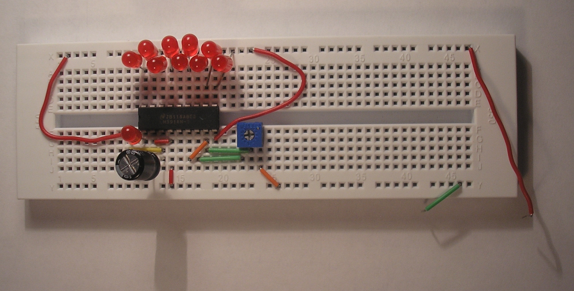
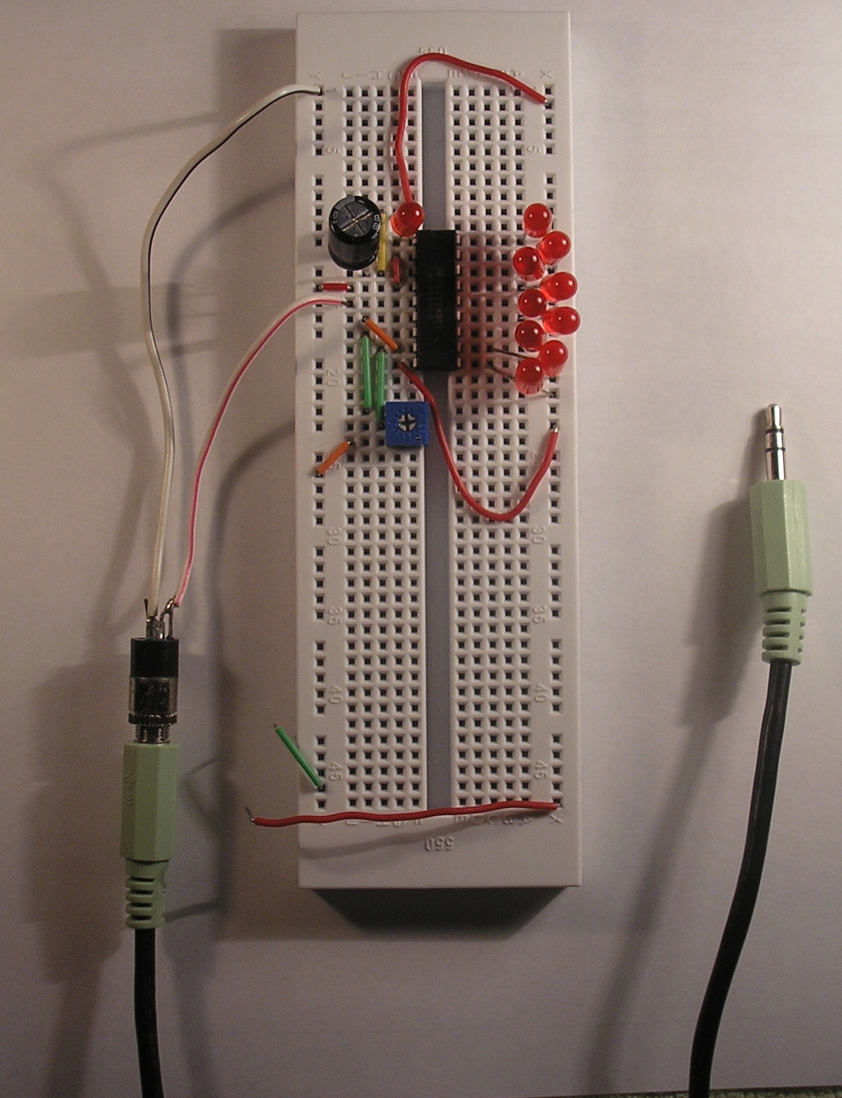
Get your LM3916 and breadboard ready. Make sure you have all the parts in the parts list.


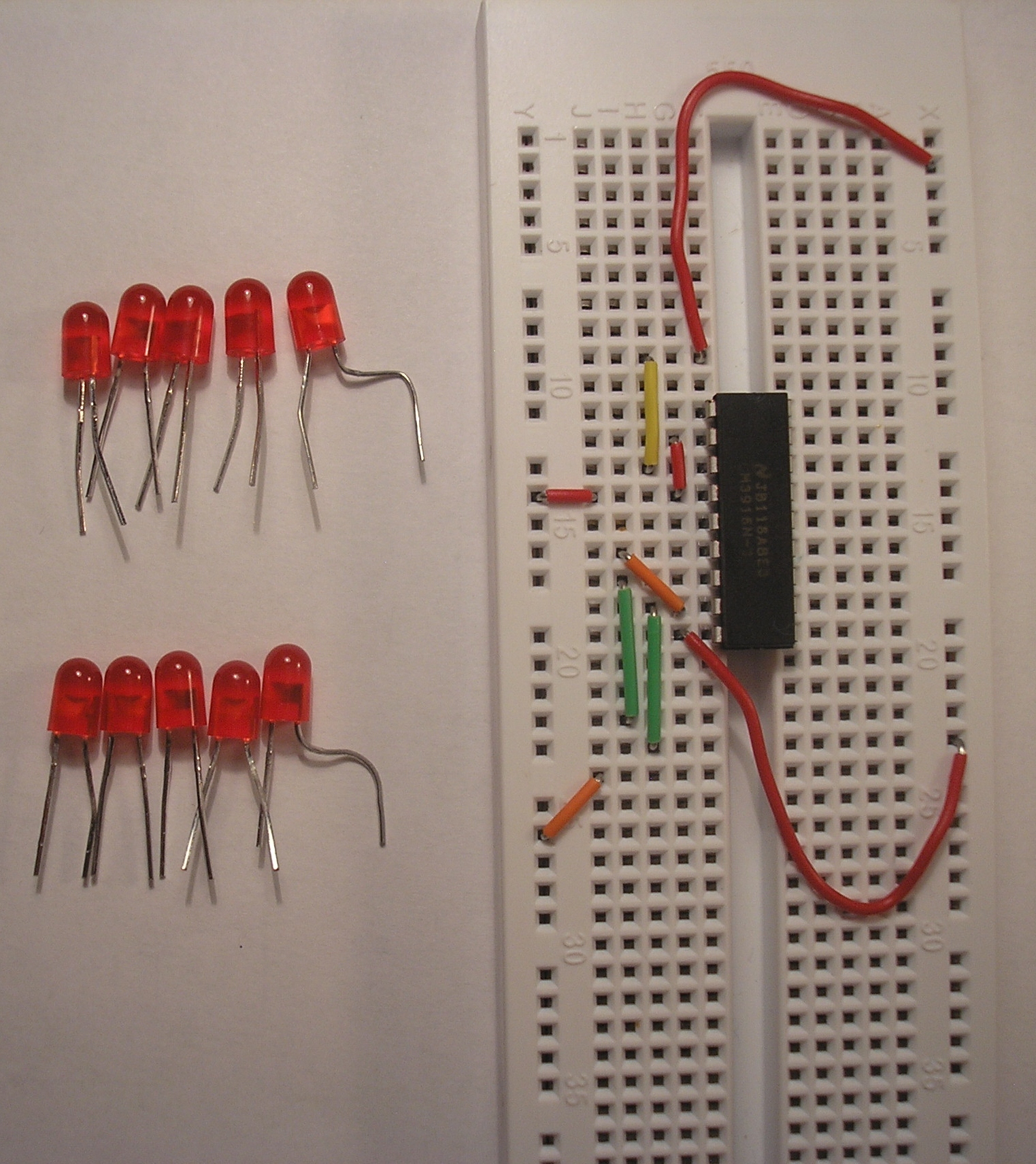
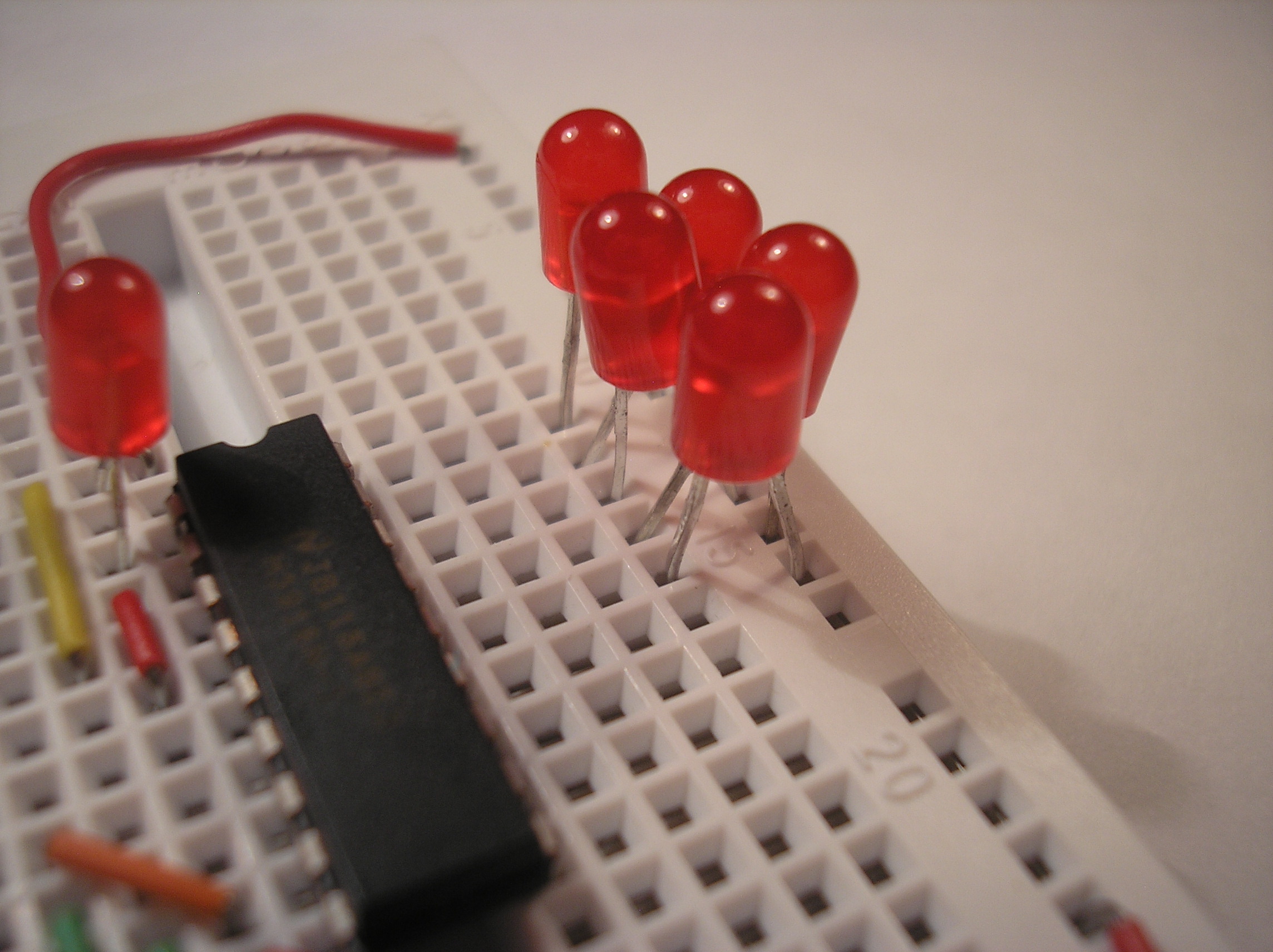
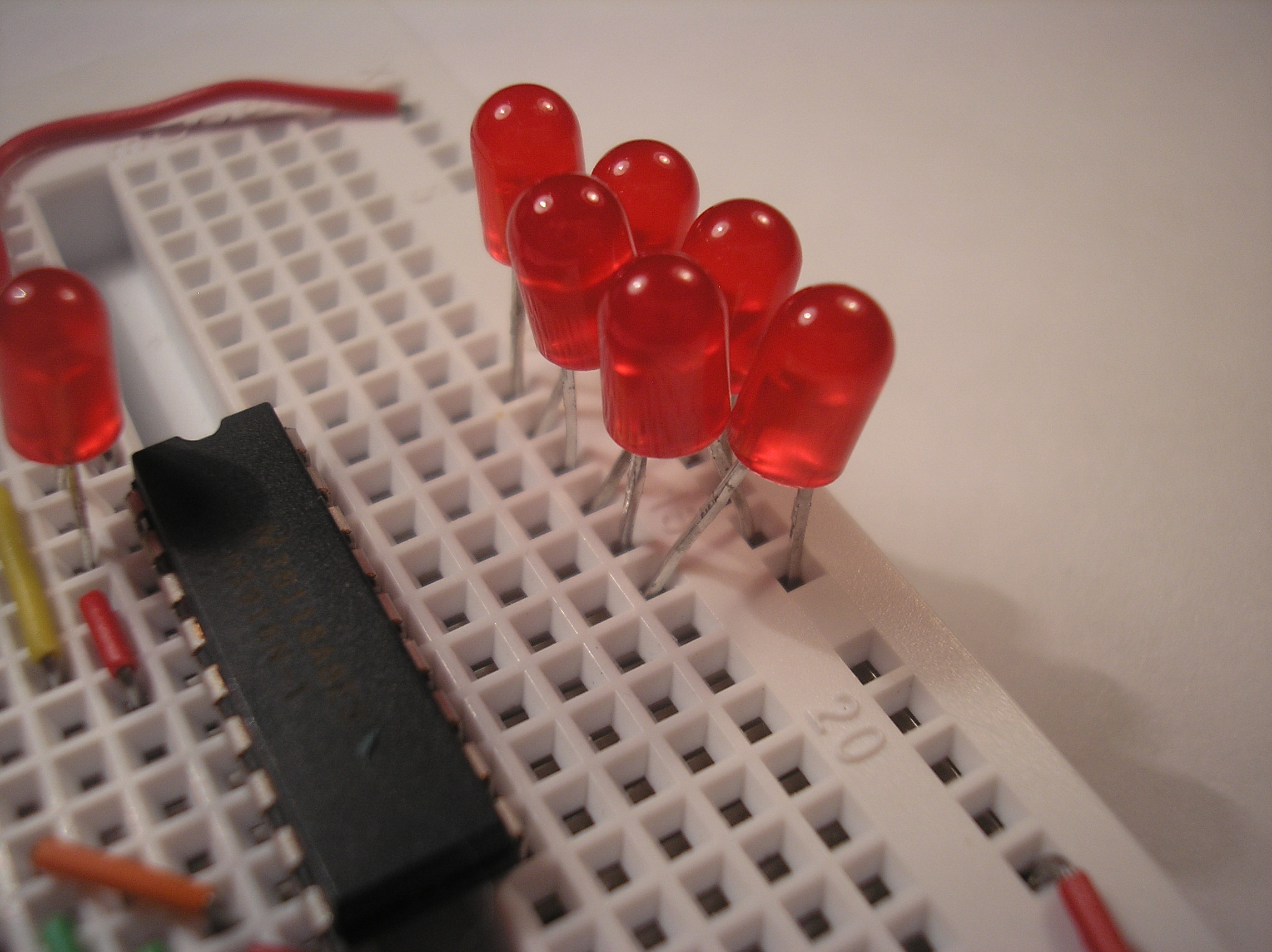
7. Collect LEDs
Collect your 10 LEDs. You can use any color LEDs that you would like. One common arrangement is LEDs 1-7: green, LEDs 8-9: yellow, LED 10: red. I used just red LEDs.
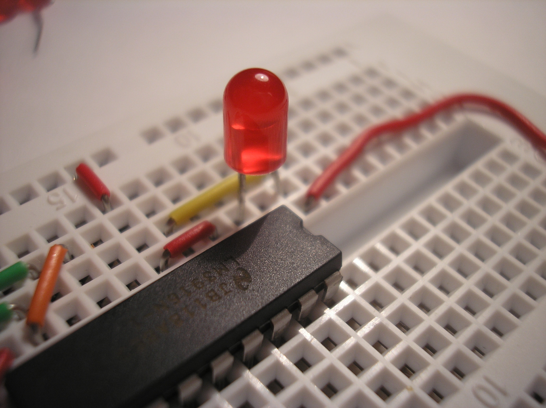
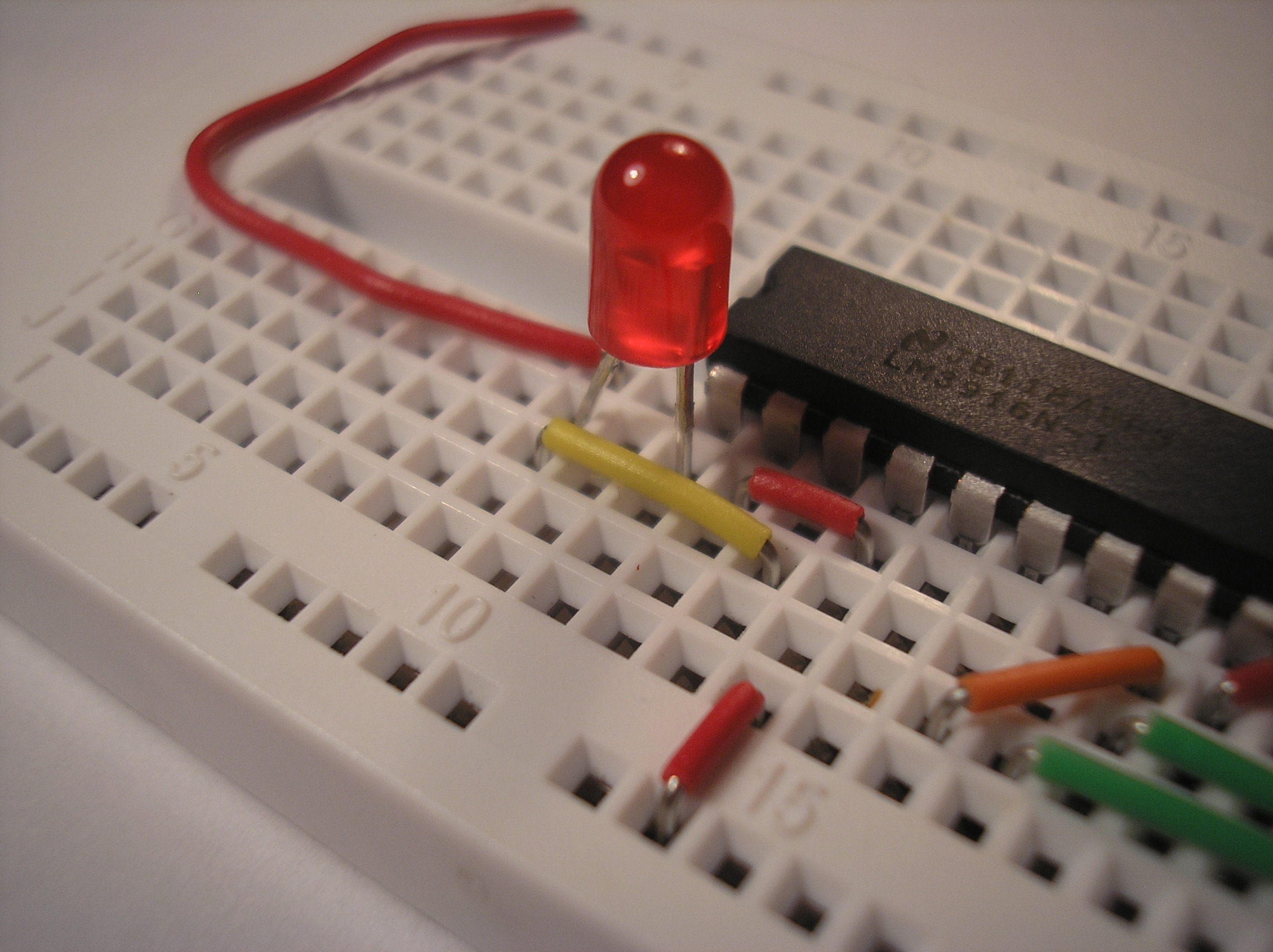
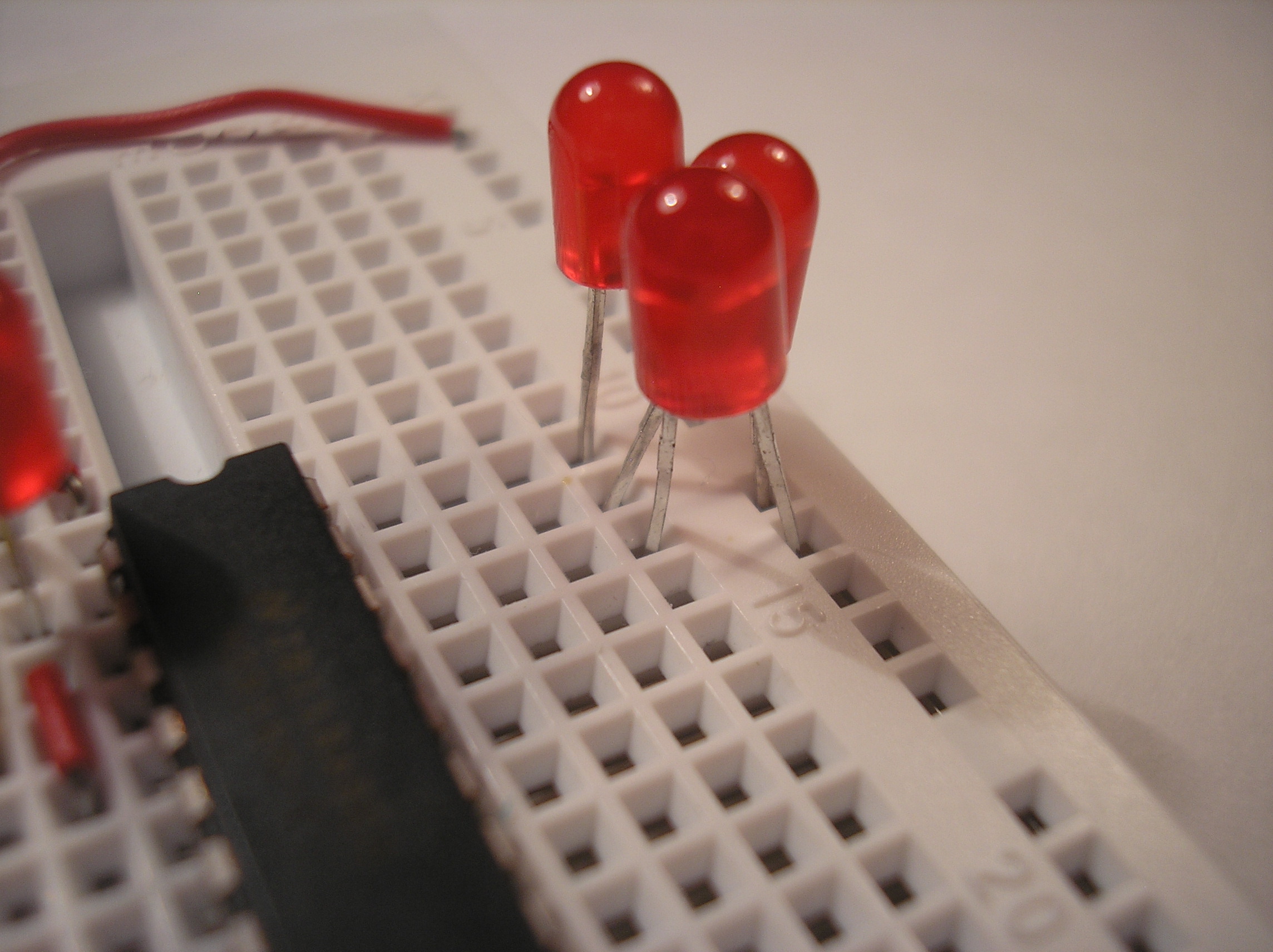
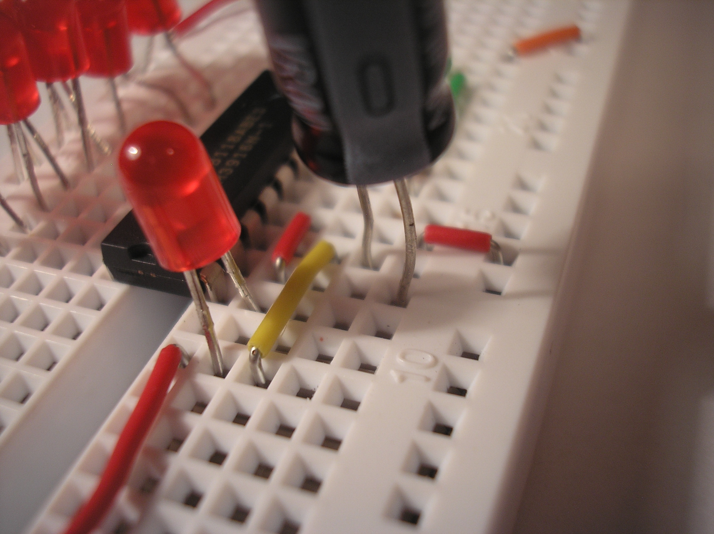
8. Insert LED1
Insert the first LED as shown. The positive leg of the LED (the long leg) connects to the red wire. The short leg goes to the LM3916 IC.
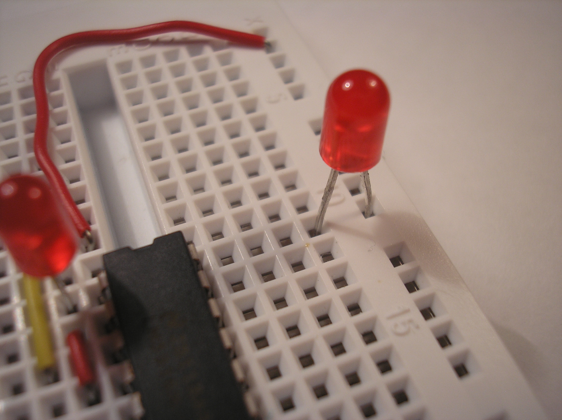
9. Insert LED2
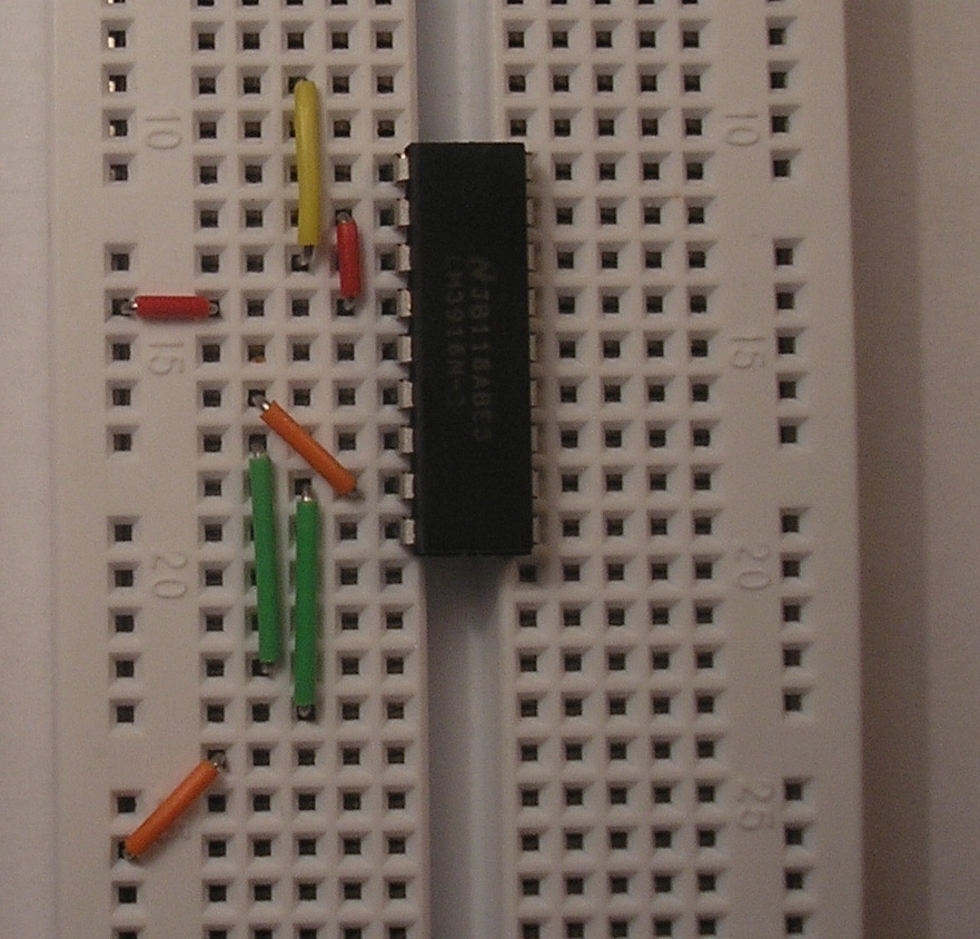
Insert the second LED. The long, positive leg goes connects to the +9V rail on the far right side of the bread board. All of the following LEDs also have their long, positive legs connected to this rail.
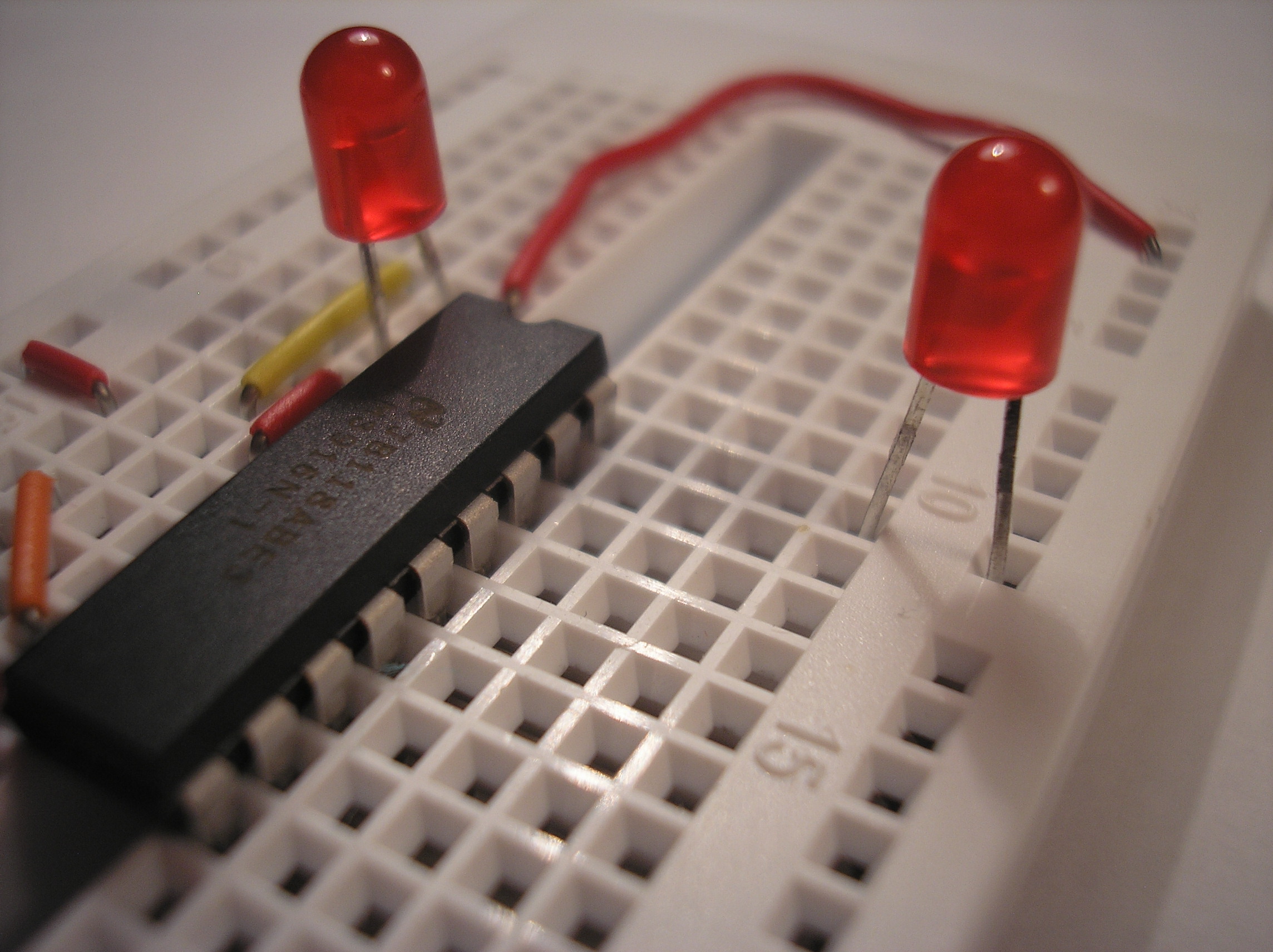
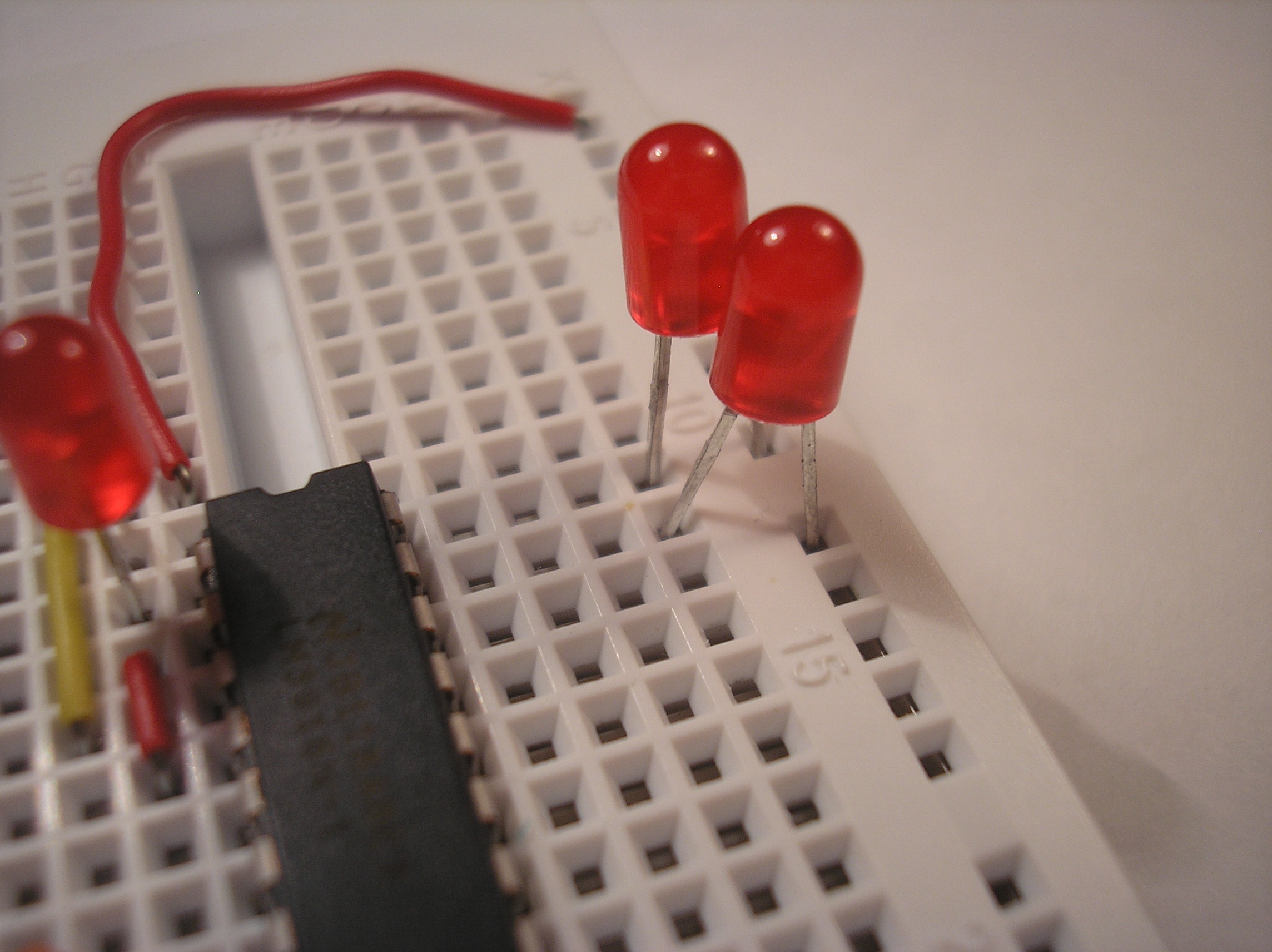
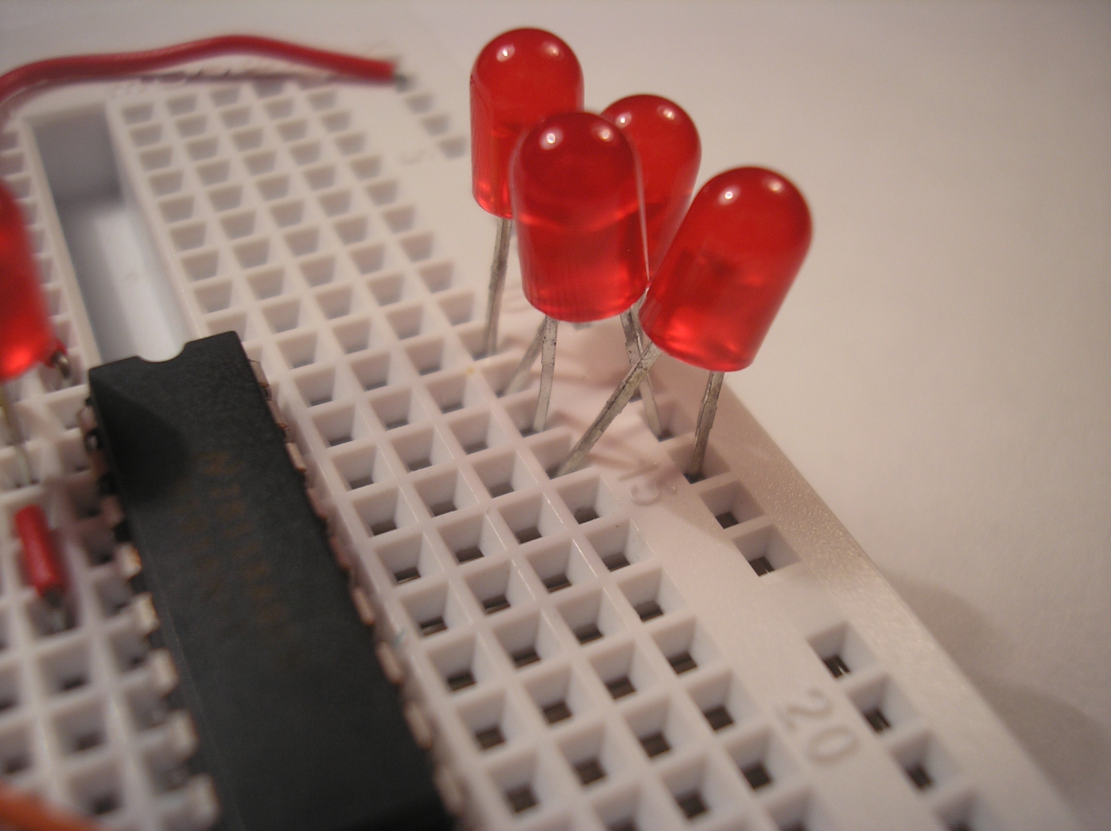
11. Insert LED4
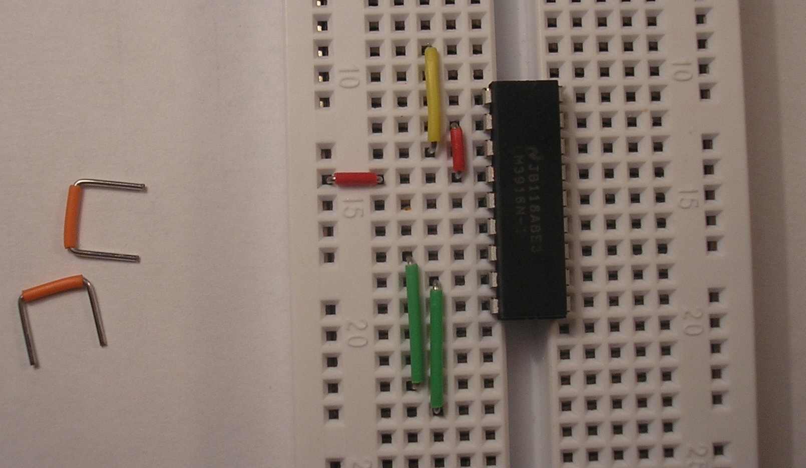
Insert the fourth LED. I'm making the LED alternate left and right so that they can squeeze together.
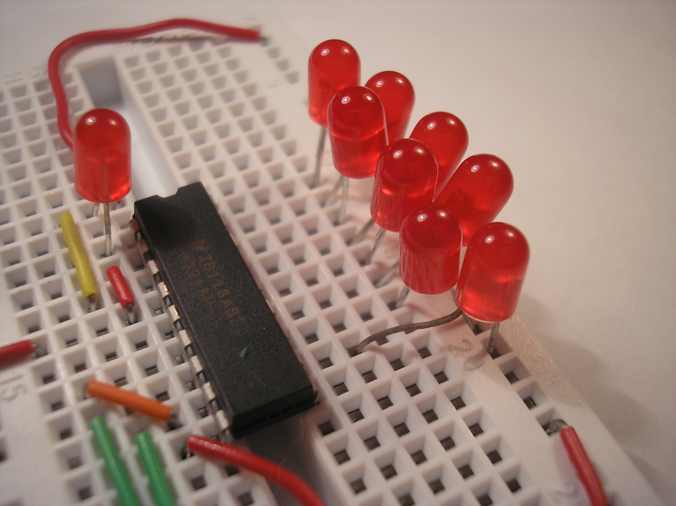
18. Insert capacitor
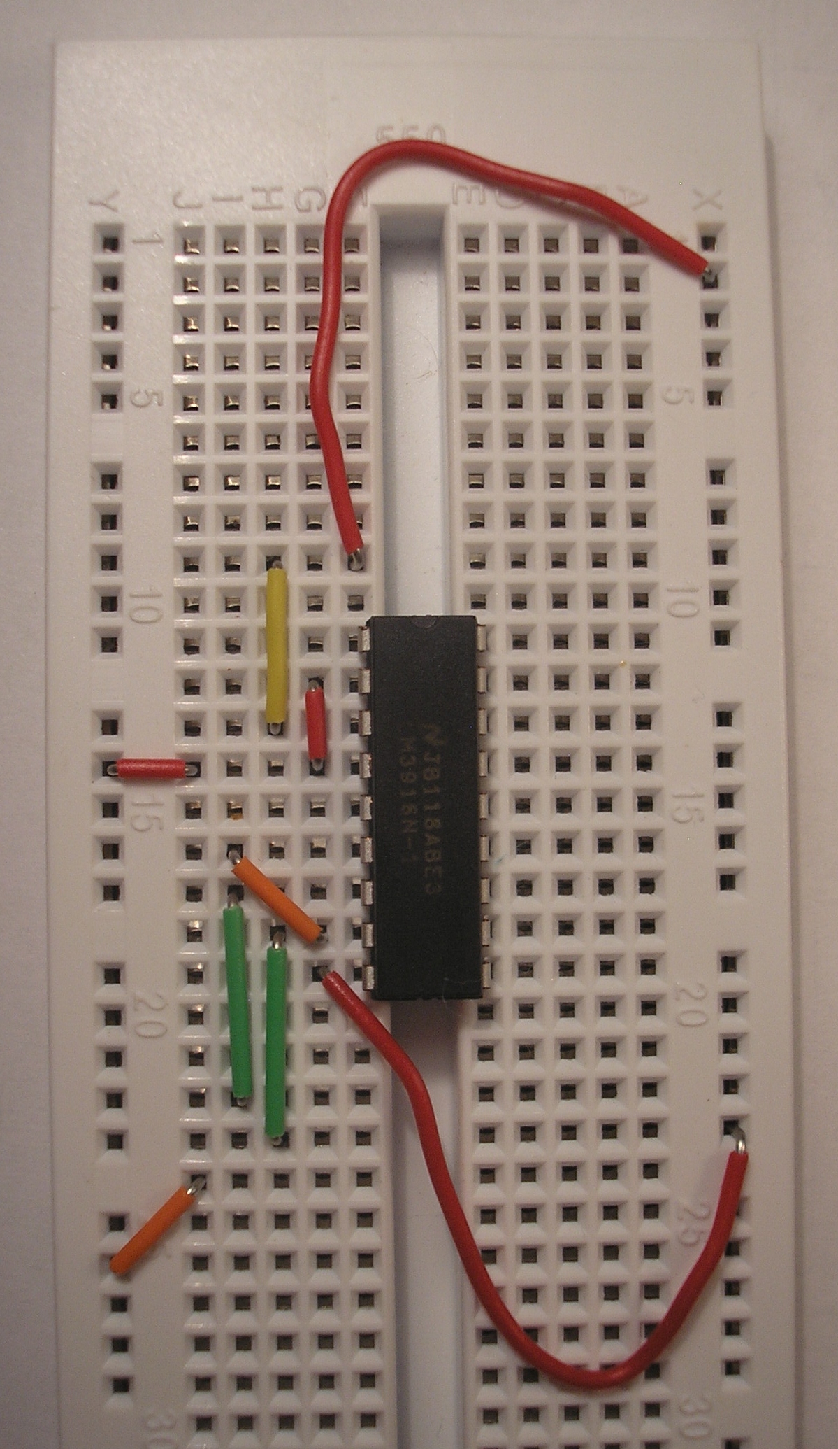
Insert the 10uF capacitor as shown. The negative leg of the capacitor (indicated by the white stripe on the side of the case) connects to pin 2 of the LM3916 IC. The positive leg connects to pin 3.
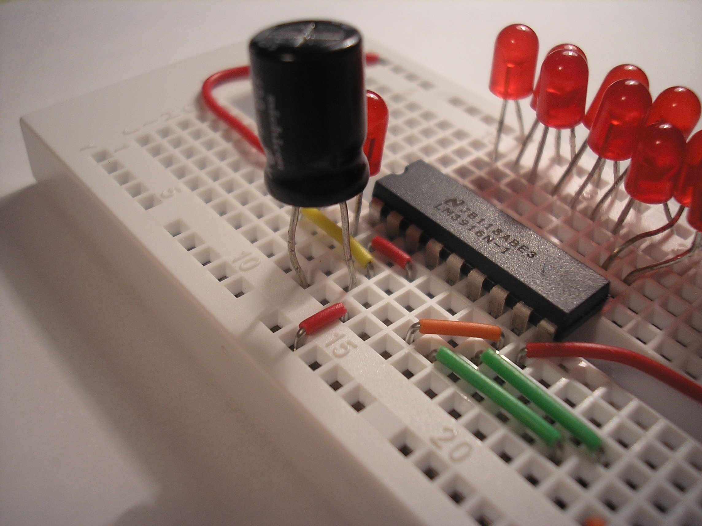
19. Insert potentiometer
Insert the trim pot (potentiometer) as shown. In this circuit, the trim pot serves a dual role. It adjusts the brightness of the LEDs as well as the maximum range of the VU meter itself.
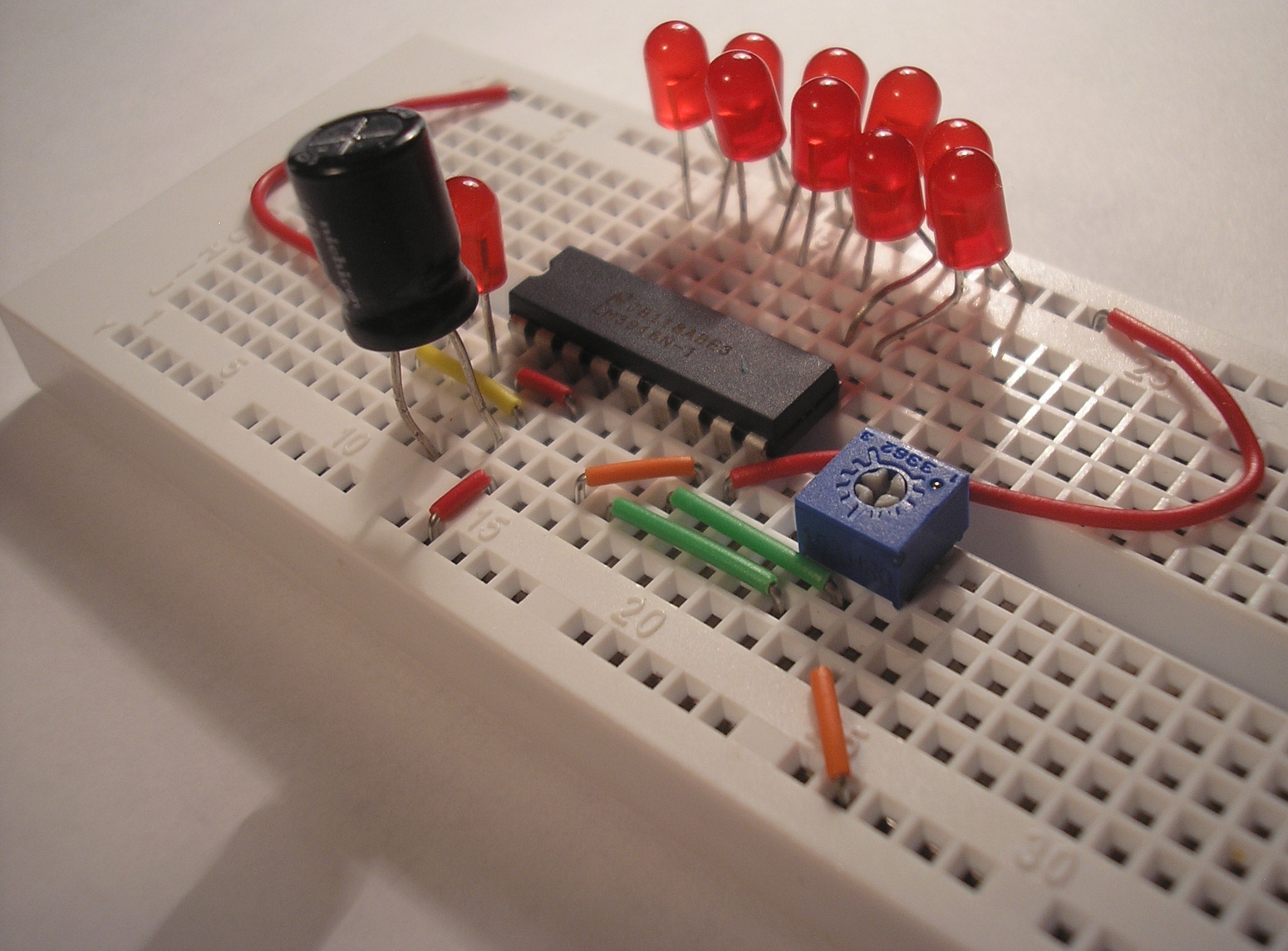
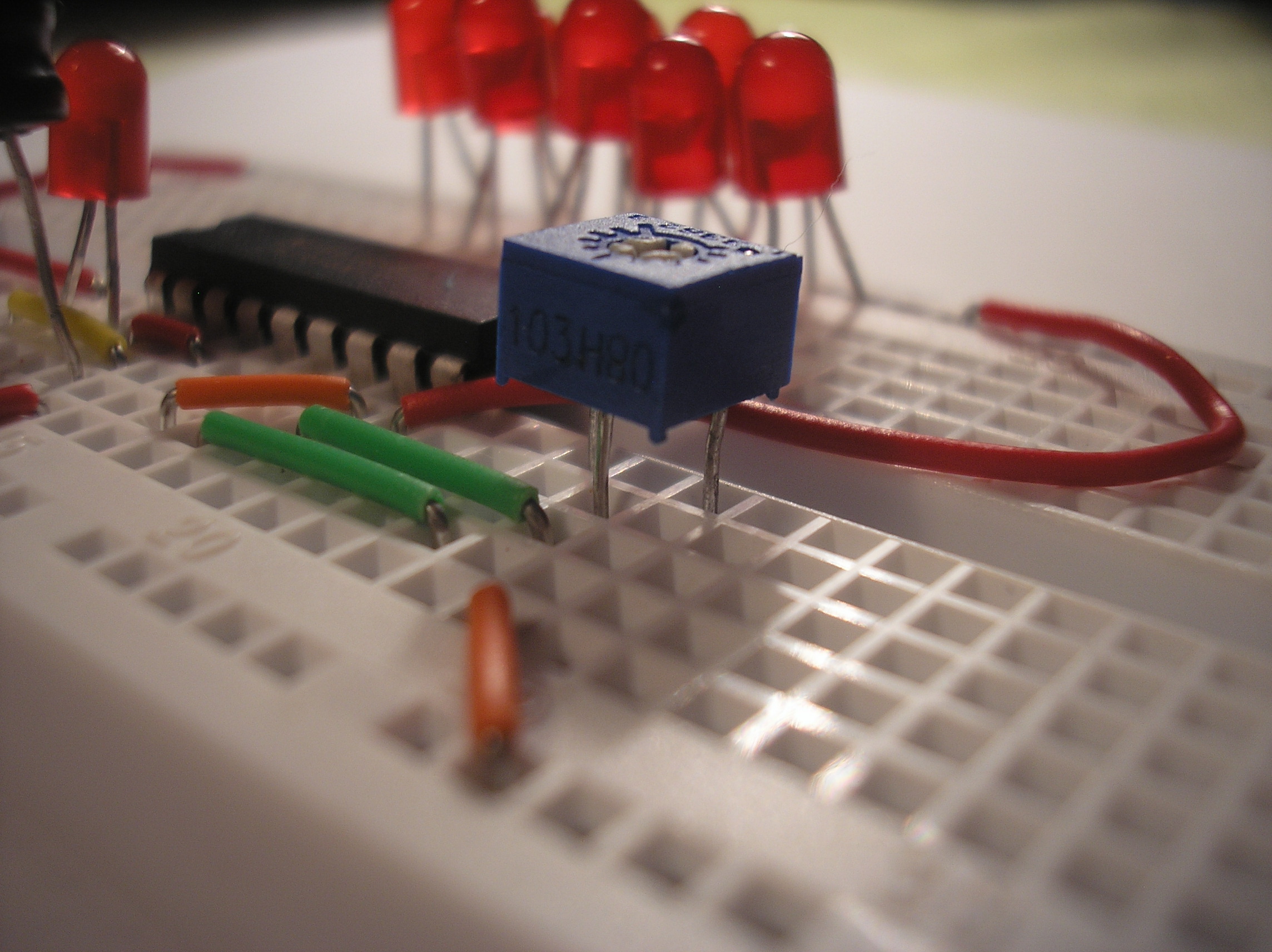
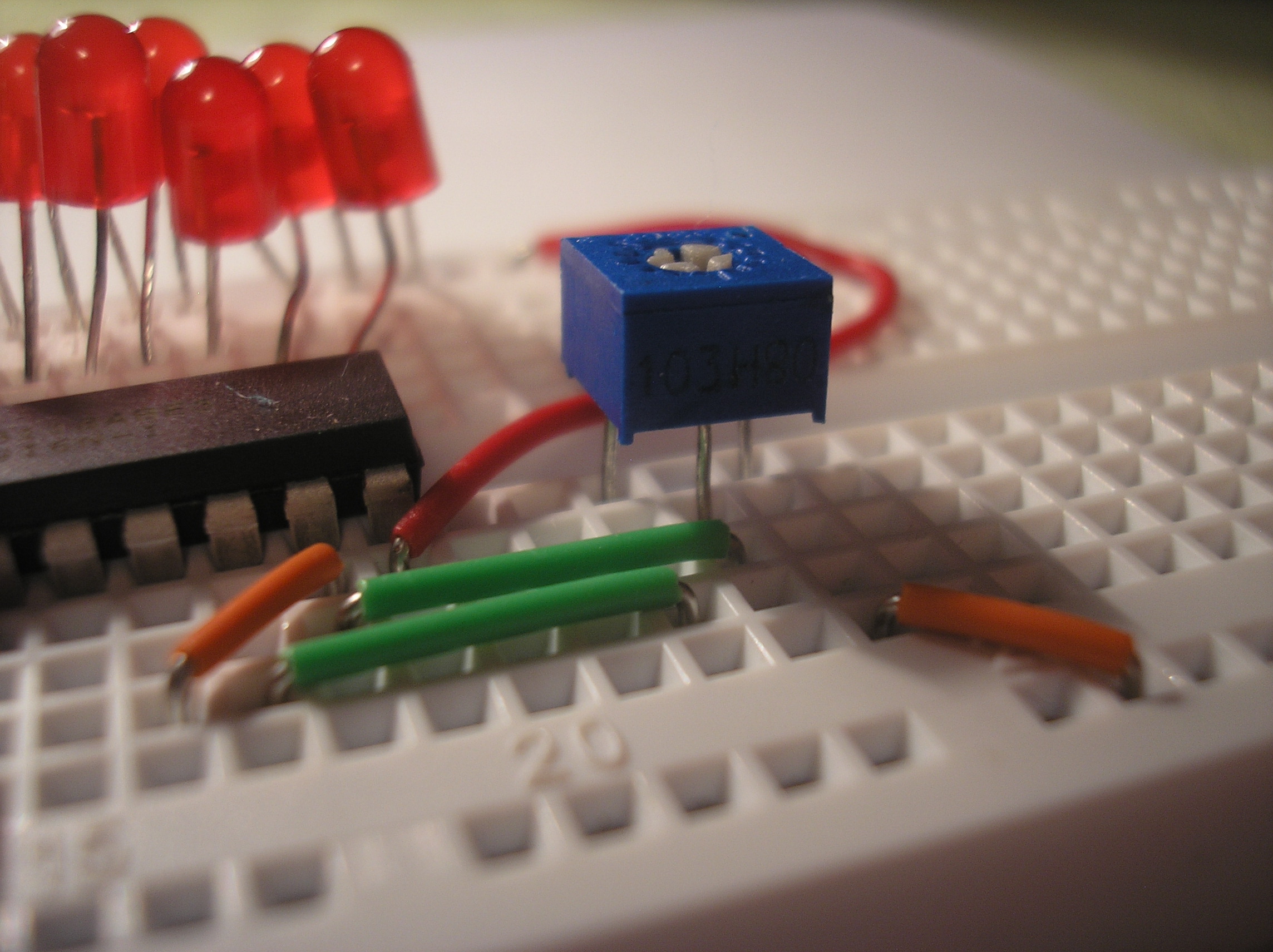
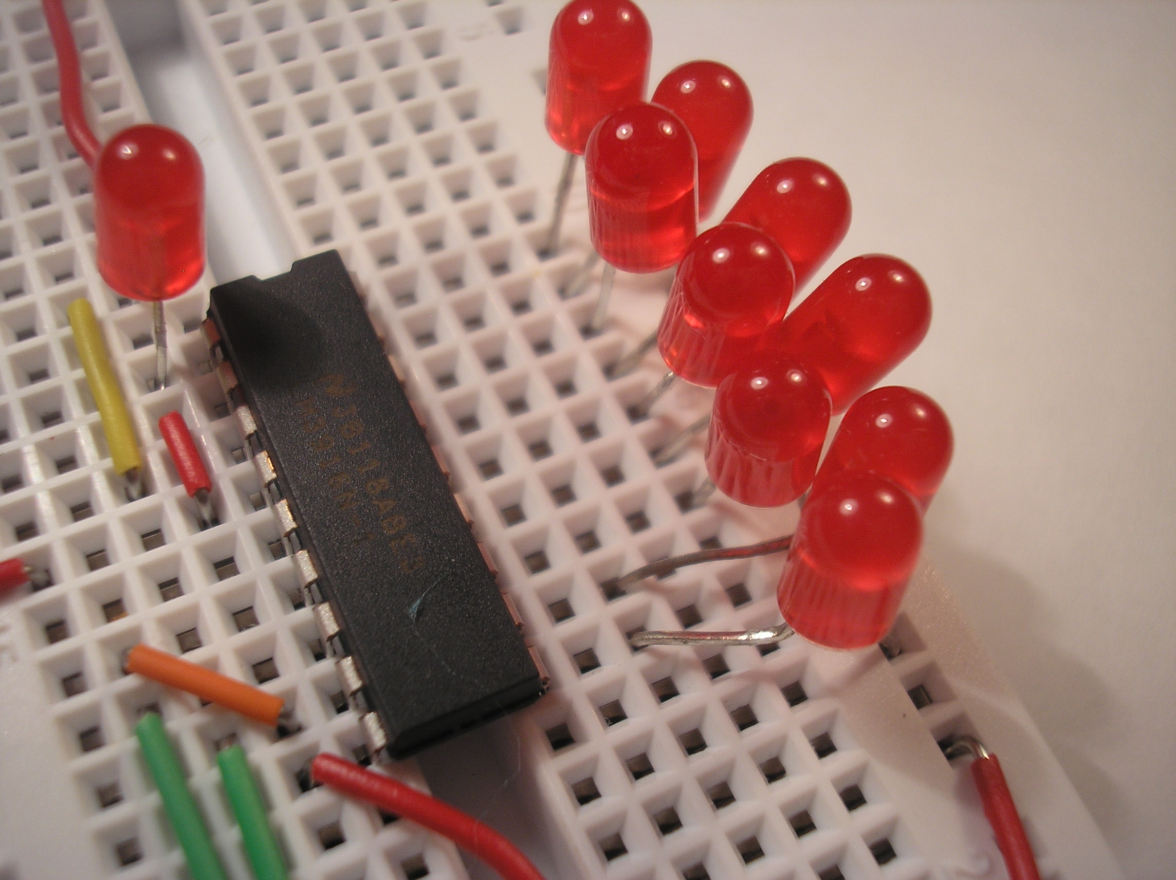
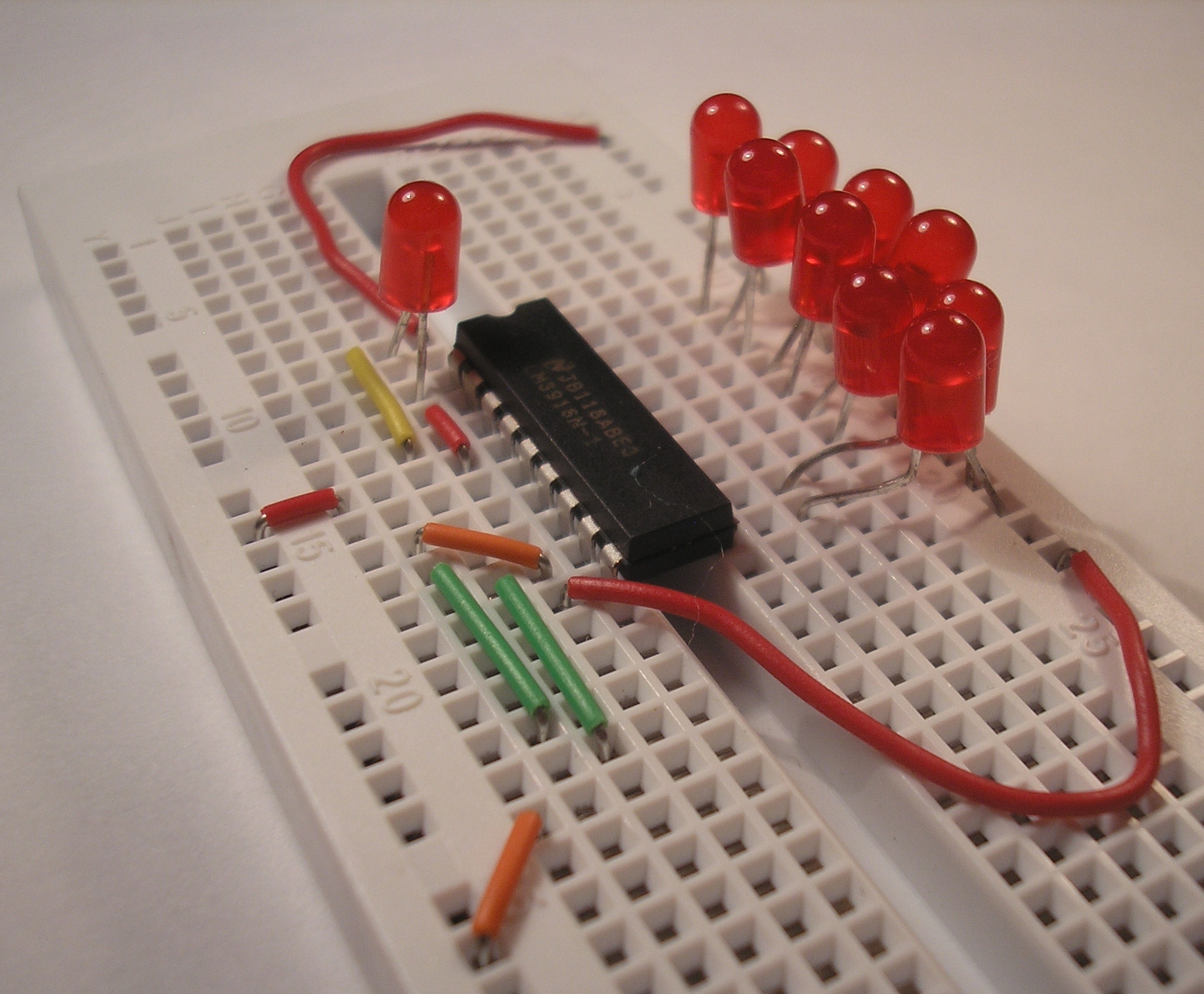
20. Insert wires
Insert a red wire into the rail that the LEDs are plugged in to. This will serve as the +9V rail. Plug a green wire into the other rail. The green wire will be ground for this circuit.
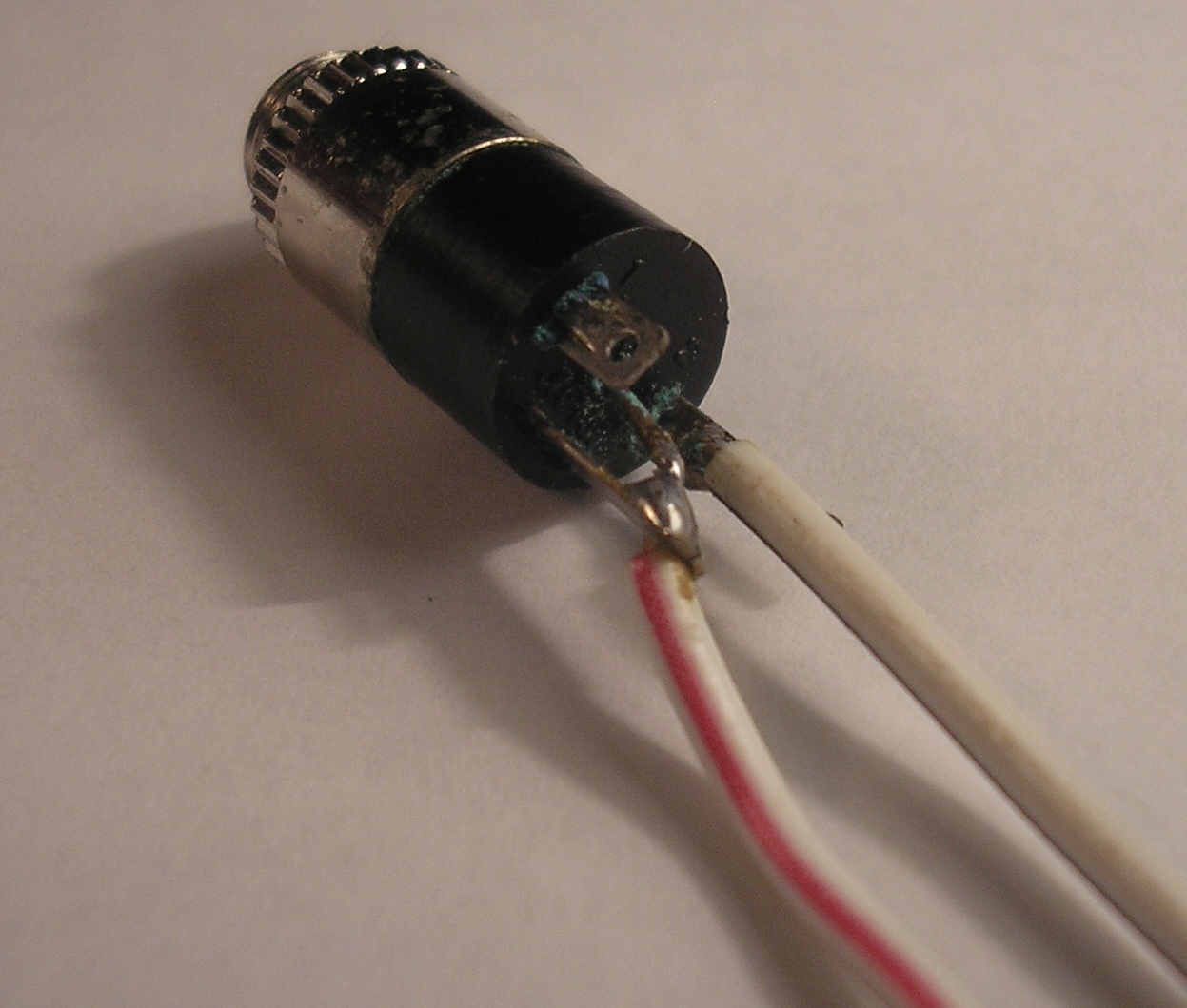
21. Solder wires to audio jack
Solder a pair of wires to the audio jack as shown. The longer terminal in the middle is the reference gound. The other two pins are stereo-left and right. You audio jack may look differently. The pin in the middle/the pin that looks different is usually the reference ground.
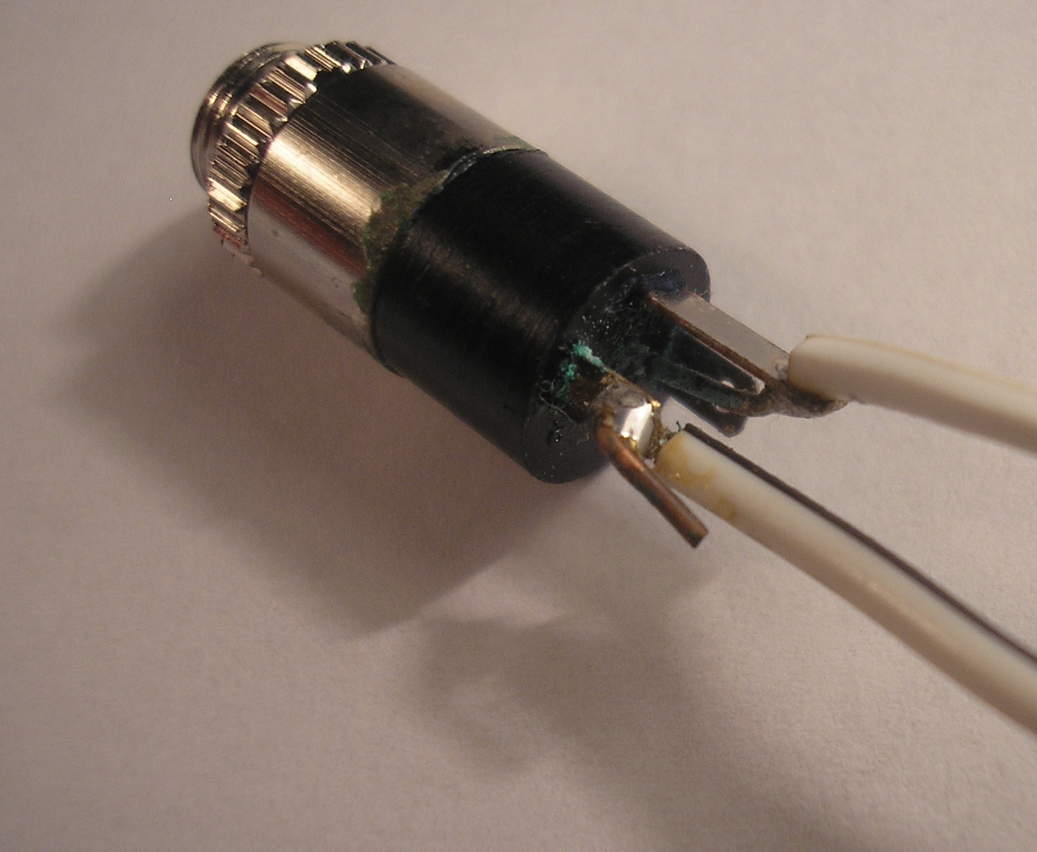
22. Note: Stereo left vs. stereo right
It doesn't matter if you use stereo left or right. If you build another VU meter, then you can display stero left on one and stereo right on the other.
23. Connect audio jack
Connect one of the audio jack's terminals to ground and the other to pin 5 of the LM3916. It doesn't matter which terminal of the audio jack goes where because the audio signal is AC and the IC only measures the peak voltages.
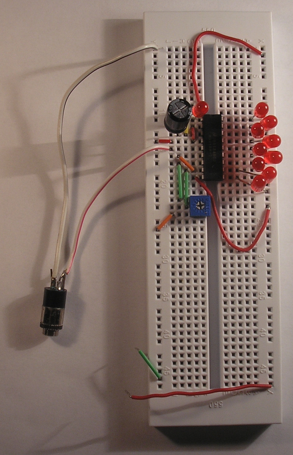
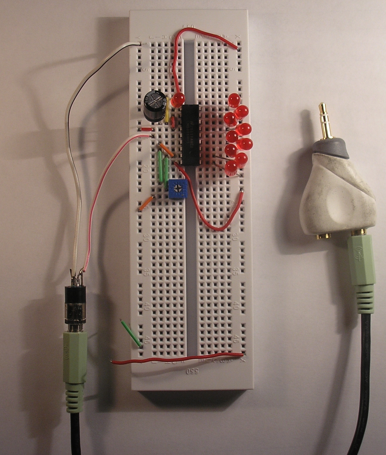
25. Plug audio cable into Y-splitter
Plug the other end of the audio cable into a Y-splitter. The male end of the Y-splitter plugs into your PC/iPod. The female end let's you plug in your headphones/speakers.
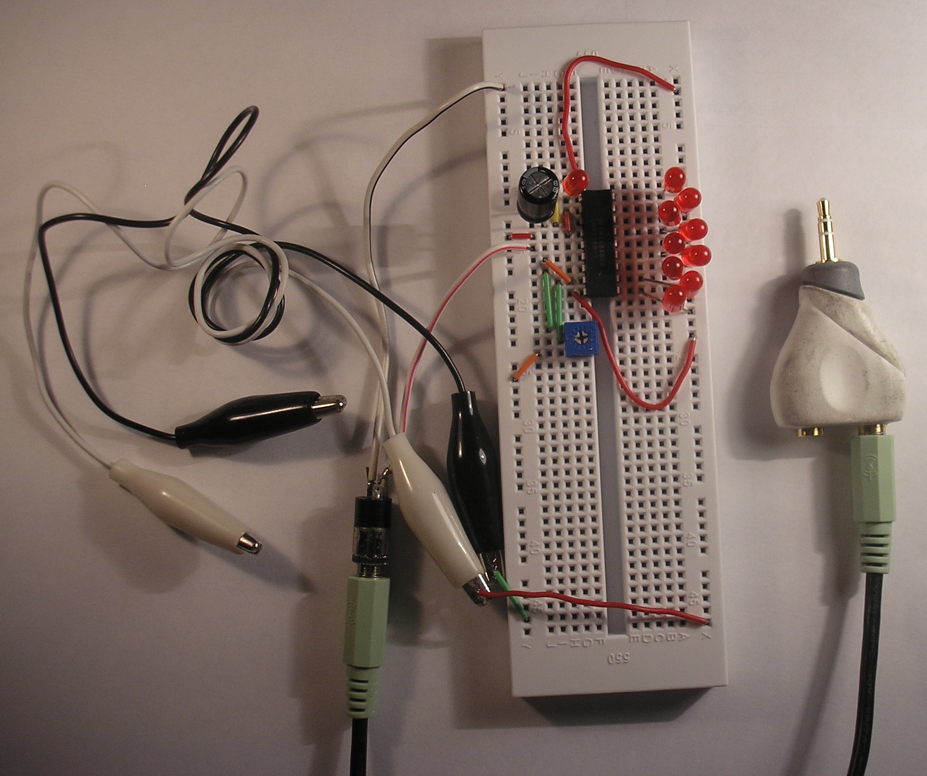
26. Connect terminals for 9V battery
Connect a pair of alligator clips to the ground and +9V wires. I used a set of black clips for ground so I could remember which clip was which polarity. You could also use a 9V clip instead of alligator clips for this step. (Connect the red wire to the right-hand rail and the black wire to the left-hand rail.)
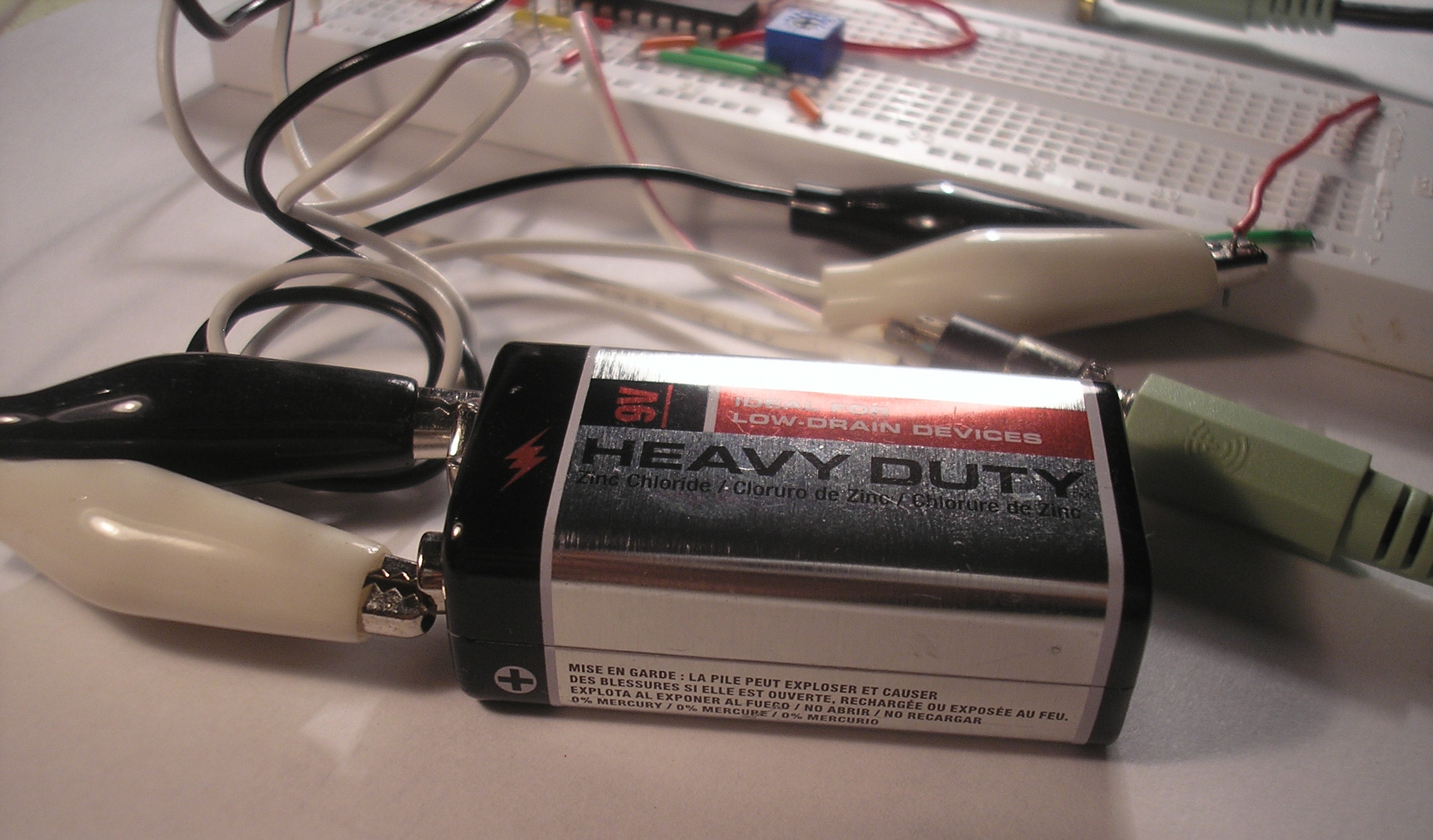
27. Connect 9V battery
Connect the ground alligator clip to the (-) side of the 9V battery, and the +9V alligator clip to the (+) side of the battery. If you are using a 9V battery clip, simply snap it onto your 9V battery.
28. Adjust potentiometer
At this point, all of the LEDs may or may not light up. Plug the Y-splitter in to your PC and play some music. Adjust the trimpot with a small flathead screwdriver so that the loudest parts of songs just barely light up all the LEDs.
29. Enjoy your new VU meter!
Enjoy your new VU meter and show it off to all your friends! Check out http://youtu.be/LT-YHW8Z-L8 to see my VU meter at work.
Download steps w/o images
Download steps w/ images
Revisions
7 - updated description
6 -
5 - added youtube link. updated line numbers.
4 - changed LED part
3 - added description to project image
2 - added file descriptions
1 - Initial project release
Add revision
blog comments powered by Disqus
Back


