-
Featured User: kurt
Open-source hardware project hosting is my passion. I spend most of my free time building neat gadgets or planning what I'll build next. I love building things, and I want to make Open Hardware Hub a place that inspires others to build, ...
-
Updates 2013 February 18
It's been a while, hasn't it? Well, that's ok because we've got a lot of updates to talk about. Most of these have been effective on the site fora couple weeks now. A few may or may not be active when this article gets posted, but they'll certainly be applied in the ...
Arduino Hardware Reset Circuit Breadboard
By: kurt
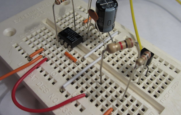
This circuit uses one pin to let you reset your Arduino in code. It pulls reset low for a couple milliseconds to ensure the Arduino has enough time to complete its reset cycle.
Download project description w/o images
Download project description w/ images
Files
- ArduinoReset.sch - Arduino Reset EAGLE Schematic
- ArduinoReset.brd - Arduino Reset EAGLE Board
- Arduino Reset.zip - Arduino Reset Gerber
- Arduino_Reset.pde - Arduino Reset Example Sketch
Bill of Materials
| Qty | Part # | Description | Schematic ID | Source | |
|---|---|---|---|---|---|
| 1 |
|
NE555P | TIMER SINGLE PRECISION,DIP8 ,0.5MHZ | IC1 | Source |
| 1 |
|
CF14JT100R | 1/4w 100 ohms 5% Carbon Film Resistors | R4 | Source |
| 1 |
|
CF14JT1K00 | 1/4w 1K ohms 5% Carbon Film Resistors | R3 | Source |
| 1 |
|
CF14JT10K0 | 1/4w 10K ohms 5% Carbon Film Resistors | R2 | Source |
| 1 |
|
CF14JT100K | AXIAL CARBON FILM RES 1/4W 100K OHMS 5% LF | R1 | Source |
| 1 |
|
EEA-GA1HR10 | CAP ALUM 0.1UF 50V 20% RADIAL | C1 | Source |
| 1 |
|
SR215C103KAR | CAPACITOR, 0.01UF, 50V | C2 | Source |
| 1 |
|
2N3904BU | TRANSISTOR, NPN 200MA TO-92 | Q1 | Source |
Download BOM w/o images
Download BOM w/ images
Steps
1. Gather parts
Gather your parts. Note that the capacitors in the picture are actually a 10pF capacitor and a 100uF capacitor. It's recommended that you use 10nF and 0.1uF capacitors as shown in the schematic.
2. Insert 555 timer
Insert the 555 timer in your breadboard. There is a small circular dent on the top of the chip that indicates pin 1. Make sure you put pin 1 on the top left side as shown.
3. Connect 555 timer to +5V
Connect pins 4 and 8 of the IC to the +5V rail on the right side of the breadboard.
4. Connect 555 timer to GND
Connect pin 1 of the IC to the GND rail on the left side of the breadboard.
5. AC couple pin 5 of the timer to ground
Place the 10nF capacitor between pin 5 of the IC and the ground rail. The value of this capacitor is not very important, and the circuit will probably still work without it.
Download steps w/o images
Download steps w/ images
Revisions
7 - fixed steps 3 and 4
6 - fixed an error in the description
5 - fixed the text for the third step
4 - none
3 - changed name to indicate this project is built on a breadboard
2 - updated description
1 - Initial project release
Add revision
blog comments powered by Disqus
Back


