-
Featured User: kurt

Open-source hardware project hosting is my passion. I spend most of my free time building neat gadgets or planning what I'll build next. I love building things, and I want to make Open Hardware Hub a place that inspires others to build, ...
-
Updates 2013 February 18
It's been a while, hasn't it? Well, that's ok because we've got a lot of updates to talk about. Most of these have been effective on the site fora couple weeks now. A few may or may not be active when this article gets posted, but they'll certainly be applied in the ...
Openbench logic sniffer pull-up/down wing
Files
- OLS_board.zip - PCB gerber files
- OLS_board__schematic.pdf - OLS_board schematic
Bill of Materials
| Qty | Part # | Description | Schematic ID | Source | |
|---|---|---|---|---|---|
| 4 | 4609X-101-103 | Resistor Network,10kOhm,2%,Bussed,+/-100 | Source | ||
| 4 |
|
BD08 | DIP SWITCH, POSITION 8 | Source | |
| 1 |
|
929500-01-36 | Pin Strip Header | Source | |
| 1 |
|
PPTC181LGBN-RC | CONN FEMALE 18POS .100" R/A TIN | Source | |
| 2 |
|
2-881545-2 | AMP SHUNT LOW PROFI | Source | |
| 1 |
|
PEC36SAAN | CONN HEADER .100 SINGL STR 36POS | Source | |
| 3 | CR0603-FX-1001ELF | RESISTOR, 0603, 1K, 1%, 0.1W | Source |
Download BOM w/o images
Download BOM w/ images
Steps
1. Have the PCB made
Grab the gerber files and send them off to a PCB manufacturer of you liking. The usual suspects located in Shenzhen have pretty good deals for small quantity orders. This time I only posted the gerber files and the schematic. You can still do what you want with it, but this board is so simple that everybody can re-create it on their own if you want to change things. If you're absolutely desperate, try searching for it on github.

2. Get the parts and fire up the soldering iron
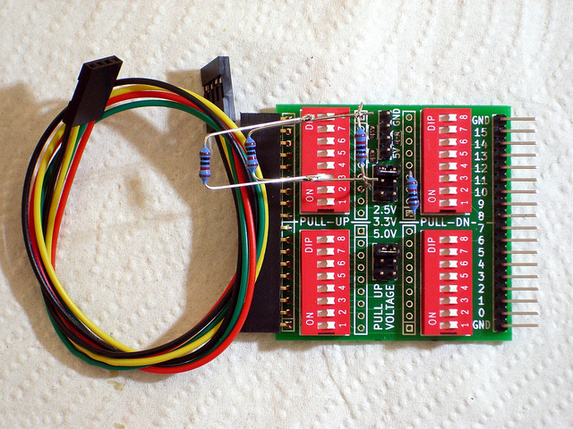
Assembly is rather simple. Everything except 3x 1k 0603 resistors is just large through-hole parts. And if you don't want to deal with the SMD parts, you can replace them with a solder bridge (now you shouldn't misplace the voltage select jumpers, or you'll probably fry your OLS). The only parts that need a bit of special care are the resistor networks. Make sure the common pin (#1) is placed into the square pad on the PCB.
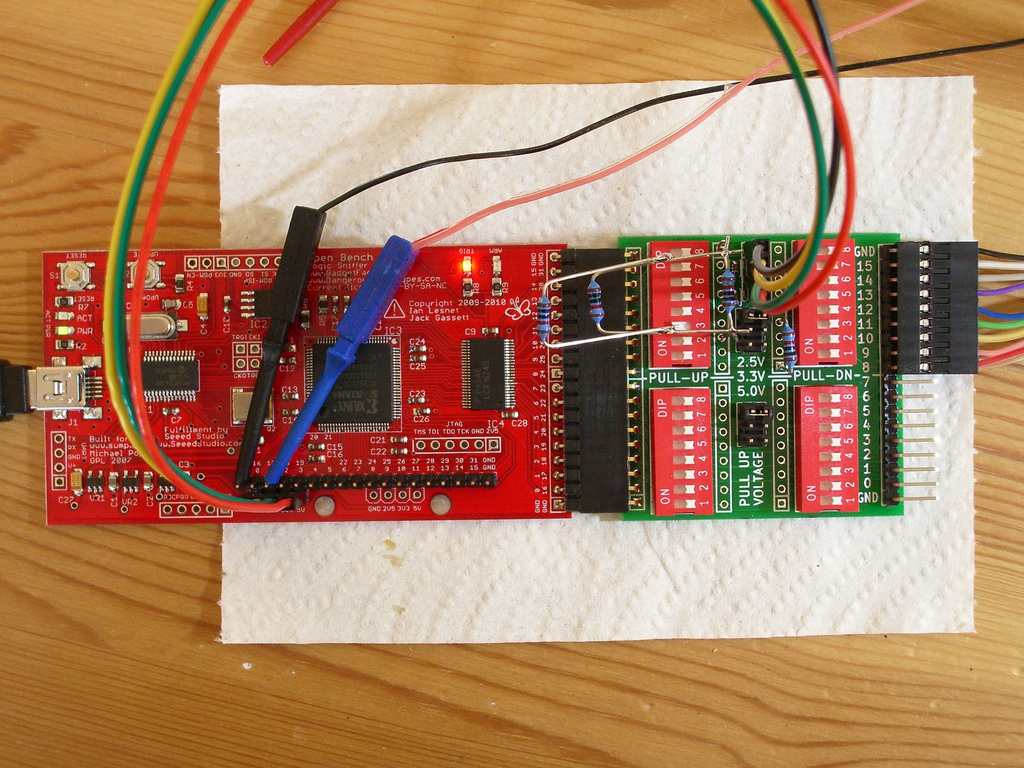
You'll have to cut the female headers to size. A file will help to clean up the edges. You'll also need a 4-wire double female header connector cable to 'steal' the pull-up voltages from the OLS board itself.
The individual 10k (brown-black-black-red) resistors you can see in the image were used for testing purposes only. The empty footprint below them will be filled with a 8-component resistor network.
3. Happy logic analyzing !
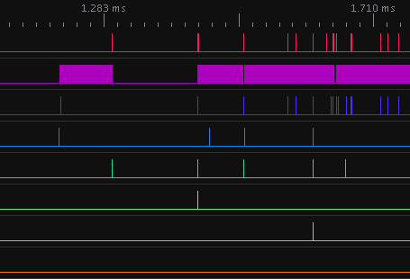
First make up your mind if you want to use pull-ups or pull-downs. In case of pull-down resistors, you can just flip the dip-switches of unused channels to ON. In case of pull-up resistors, you have to make sure the pull-up voltage is compatible with the signals you use. The board has two banks, so you can choose e.g. 2.5V for channels 0-7 and 5.0V for channels 8-15. Make sure to enable either pull-up or pull-down resistors on _all_ unused channels.
Now you shouldn't see any signals on unconnected logic probes appearing out of nowhere anymore.
Sidenote: YES, you can just use a piece of wire, connect it to GND and clip all unused logic probe hooks to it. It can be done, but isn't funny at all. A) these probe clips have a life of their own and like to go somewhere else. You'll hear a tiny 'click' when it happens, B) you'll end up with a big mess of wires. And you don't want that either ;-)


Download steps w/o images
Download steps w/ images
Revisions
2 - Added more logic analyzer traces.
1 - Initial project release
Add revision
blog comments powered by Disqus
Back


