-
Featured User: kurt

Open-source hardware project hosting is my passion. I spend most of my free time building neat gadgets or planning what I'll build next. I love building things, and I want to make Open Hardware Hub a place that inspires others to build, ...
-
Updates 2013 February 18
It's been a while, hasn't it? Well, that's ok because we've got a lot of updates to talk about. Most of these have been effective on the site fora couple weeks now. A few may or may not be active when this article gets posted, but they'll certainly be applied in the ...
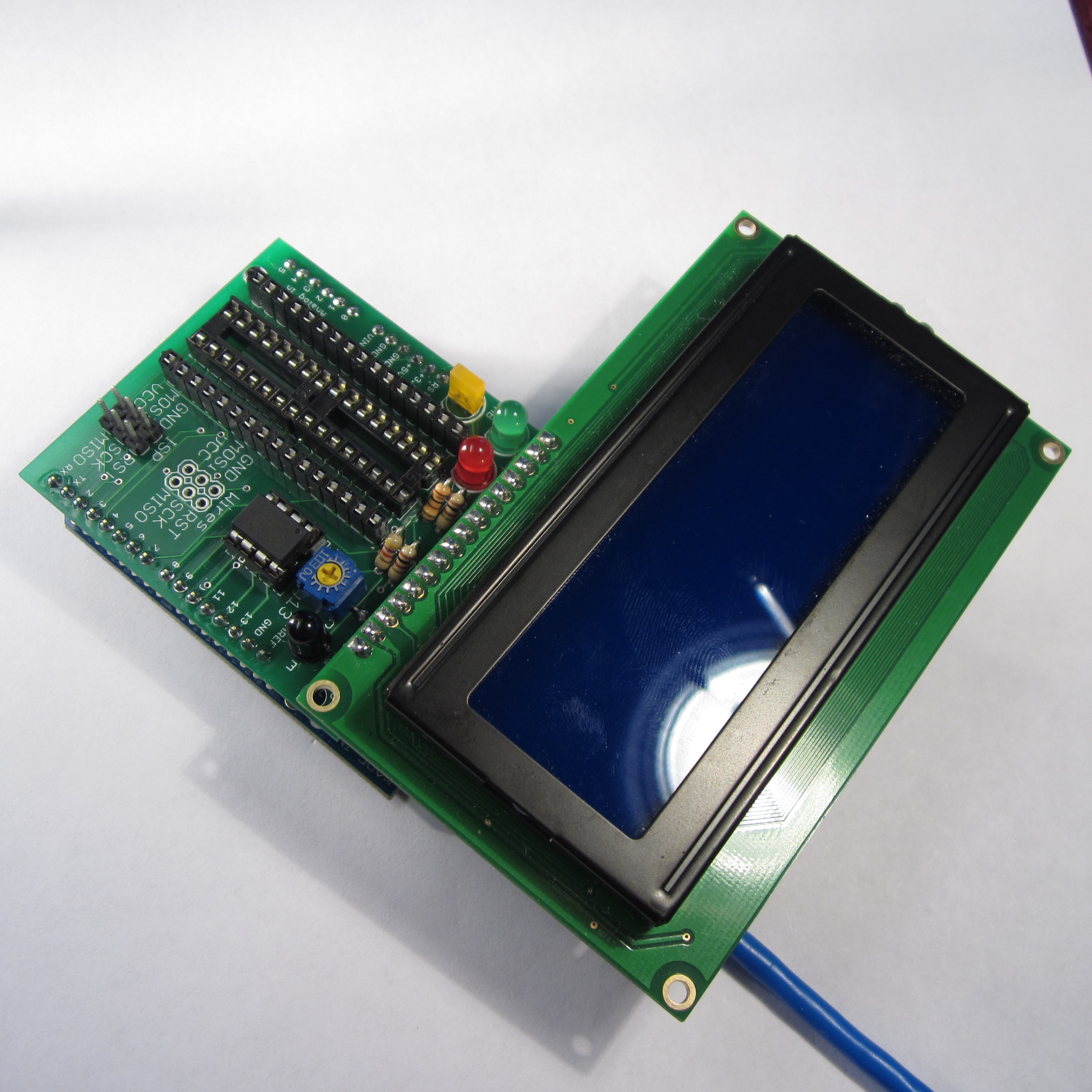
Scavenger Hunt Beacon Decoder and AVR Programmer
Files
- Scavenger Hunt Beacon Decoder V1.zip - Scavenger Hunt Beacon Decoder GERBER
- Scavenger Hunt Beacon Decoder.sch - Scavenger Hunt Beacon Decoder EAGLE Schematic
- Scavenger Hunt Beacon Decoder.brd - Scavenger Hunt Beacon Decoder EAGLE Board
- Scavenger_Beacon_Decoder.pde - Scavenger Hunt Beacon Decoder Arduino Sketch
Bill of Materials
| Qty | Part # | Description | Schematic ID | Source | |
|---|---|---|---|---|---|
| 1 |
|
WP7113LID | 5MM LOW CURRENT RED LED, LAMP THOLE, BULK | LED_ERR | Source |
| 1 |
|
WP7113CGCK | 5mm Green LED,Water Clear/Domed Lens, PB Free | LED_PROG | Source |
| 1 |
|
OVLGY0C9B9 | LED, 5MM, TAPERED, YELLOW | LED_HB | Source |
| 3 |
|
CF14JT100R | 1/4w 100 ohms 5% Carbon Film Resistors | R1, R2, R3 | Source |
| 1 |
|
CF14JT4K70 | 1/4w 4.7K ohms 5% Carbon Film Resistors | R4 | Source |
| 1 |
|
CT6EP103 | TRIMMER 10K OHM 0.5W TH | P1 | Source |
| 1 |
|
LCD Display | 20 x 4 Blue LCD Character Display | Source | |
| 1 | PT334-6B | PHOTOTRANSISTOR 5MM BLACK AXIAL | PQ | Source |
Download BOM w/o images
Download BOM w/ images
Steps
6. Solder LEDs
The LEDs should line up with their outlines on the board. The LEDs I used look different from the ones in the parts list, but any LED should work.
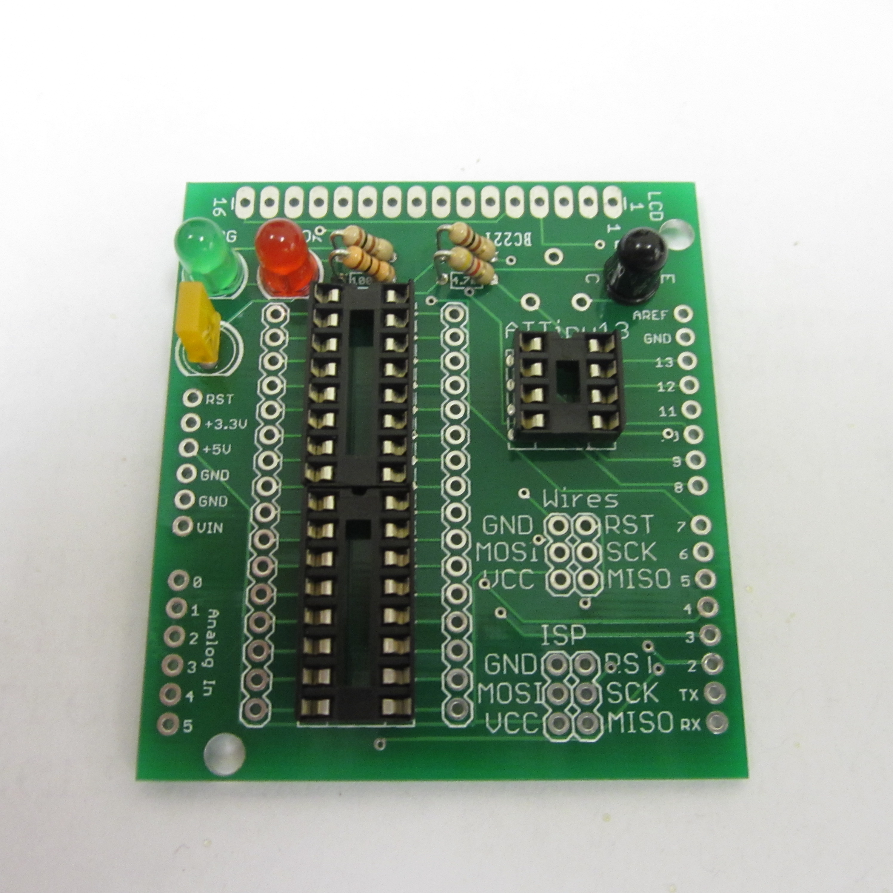
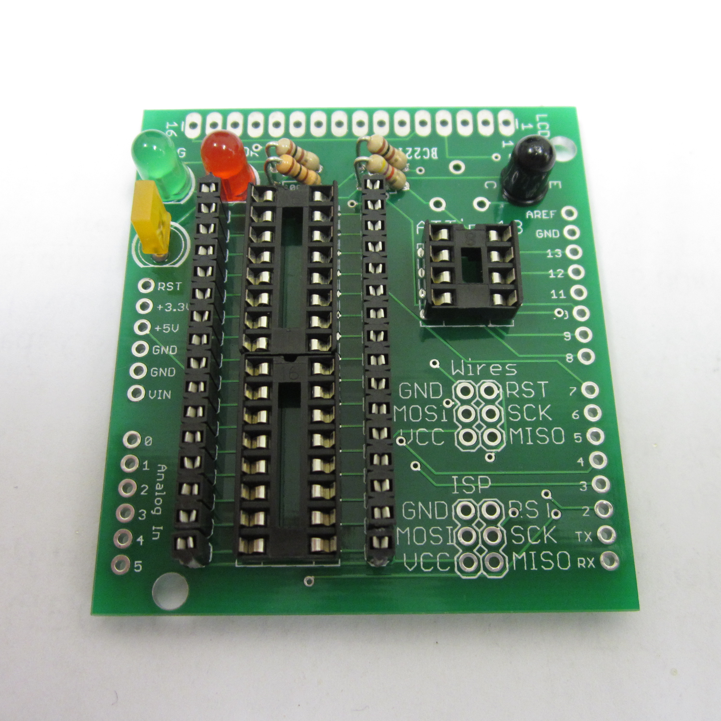
7. Solder Female Headers
Solder the female headers on either side of the two big IC sockets. These headers connect directly to the IC pins closest to each socket. Wires should be soldered into the 6 holes marked "Wires". The free ends of these wires can be inserted into these female headers to configure the board so that it can program any AVR microcontroller inserted into the large IC sockets.
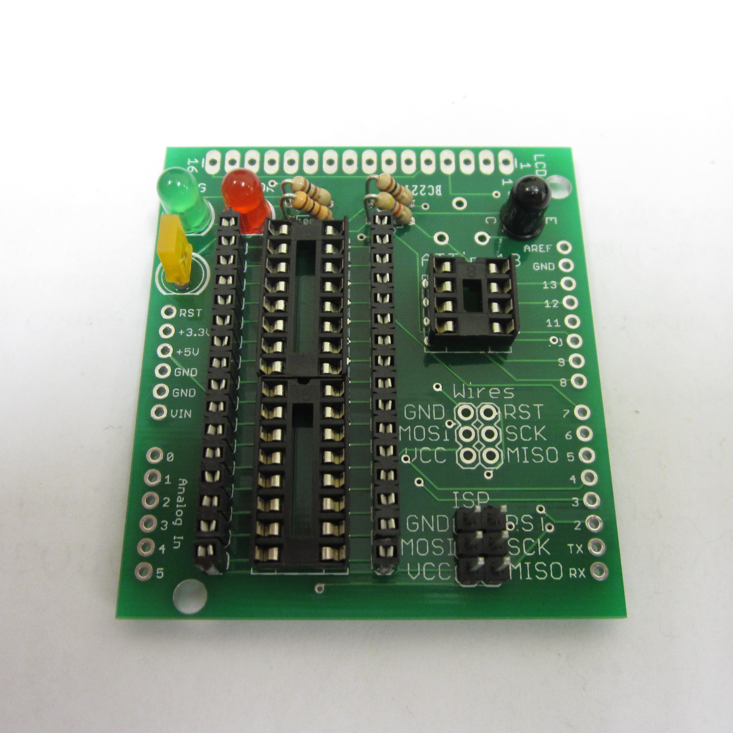
8. Solder ICSP Header
Solder two 3-pin male header strips where the board is labeled ISP. (It should be labeled ICSP. That is a typo on the board artwork.)
9. Solder Female Header and Potentiometer
Solder another female header strip across the top of the board. This header strip is where the LCD screen will plug in. Solder the potentiometer in place. You will probably have to bend the legs of the potentiometer to get them to fit in the holes. This potentiometer adjusts the contrast of the LCD screen. If you can't see any characters on the LCD screen, try adjusting this to make them show up.

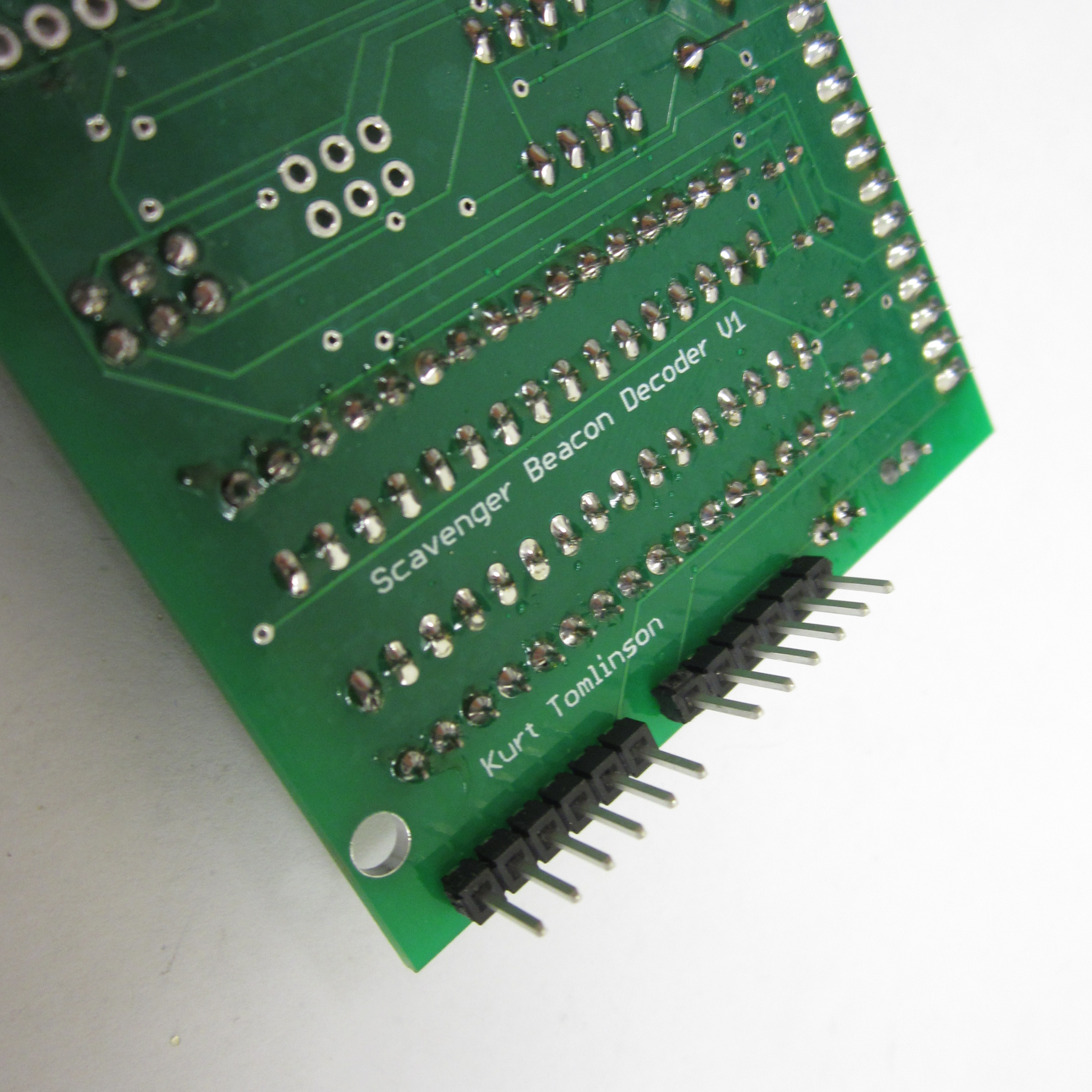
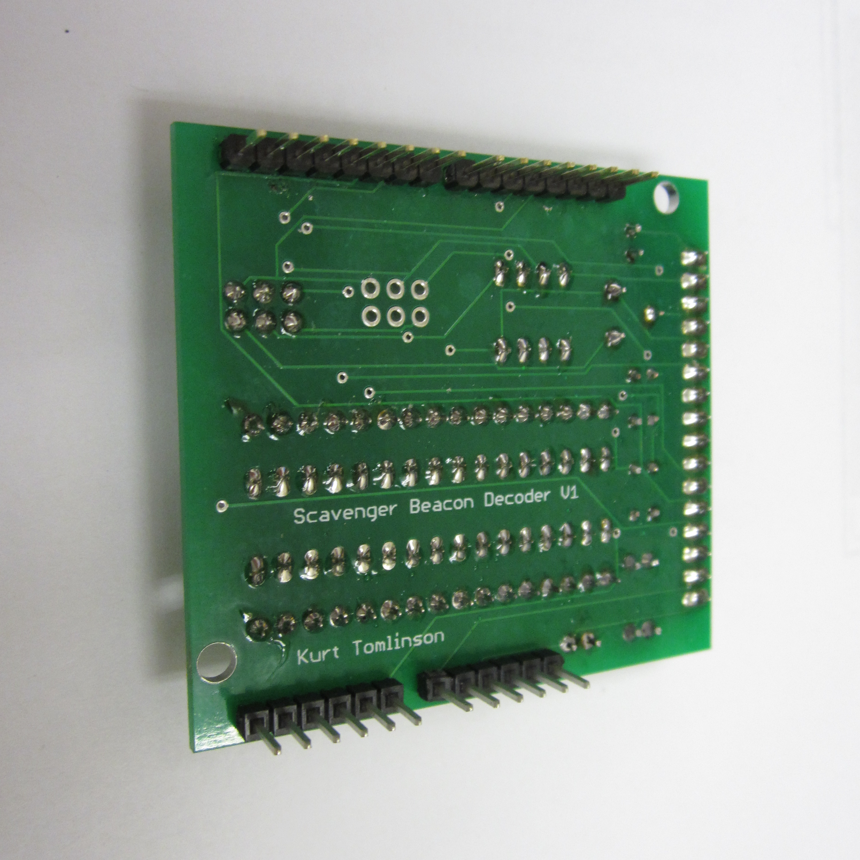
10. Solder Male Headers
Solder the make headers on both sides of the board. The headers should point down so that they can be inserted into the female headers on the Arduino.
Download steps w/o images
Download steps w/ images
Revisions
2 -
1 - Initial project release
Add revision
blog comments powered by Disqus
Back


