-
Featured User: kurt

Open-source hardware project hosting is my passion. I spend most of my free time building neat gadgets or planning what I'll build next. I love building things, and I want to make Open Hardware Hub a place that inspires others to build, ...
-
Updates 2013 February 18
It's been a while, hasn't it? Well, that's ok because we've got a lot of updates to talk about. Most of these have been effective on the site fora couple weeks now. A few may or may not be active when this article gets posted, but they'll certainly be applied in the ...
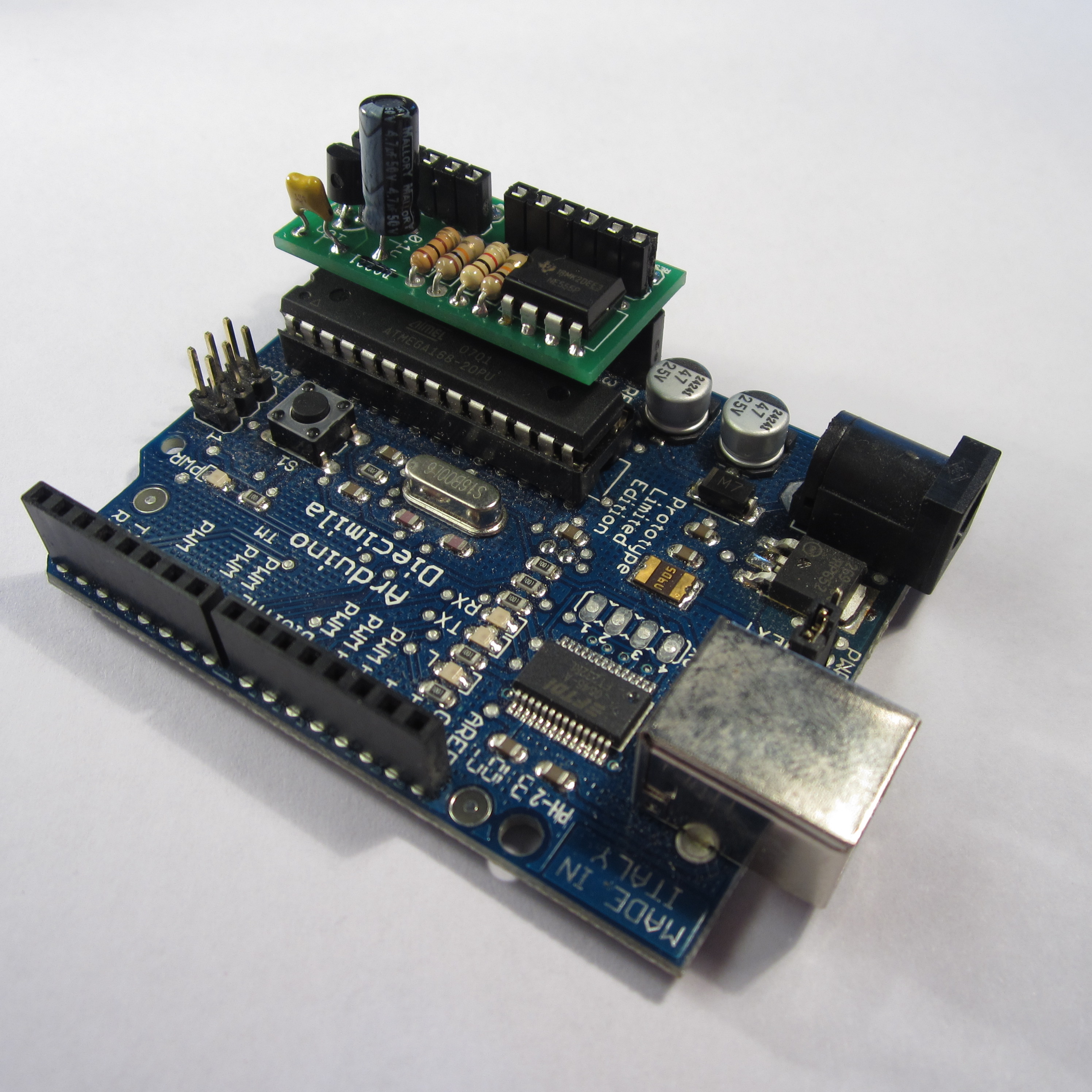
Arduino Hardware Reset Circuit PCB
Files
- Arduino_Reset.pde - Arduino Reset Sketch
- ArduinoReset.sch - Arduino Reset EAGLE Schematic
- ArduinoReset.brd - Arduino Reset EAGLE Board
- Arduino Reset V1.zip - Arduino Reset GERBER
Bill of Materials
| Qty | Part # | Description | Schematic ID | Source | |
|---|---|---|---|---|---|
| 1 |
|
NE555P | TIMER SINGLE PRECISION,DIP8 ,0.5MHZ | IC1 | Source |
| 2 |
|
CF14JT10K0 | 1/4w 10K ohms 5% Carbon Film Resistors | R1, R2 | Source |
| 1 |
|
CF14JT1K00 | 1/4w 1K ohms 5% Carbon Film Resistors | R3 | Source |
| 1 |
|
CF14JT100R | 1/4w 100 ohms 5% Carbon Film Resistors | R4 | Source |
| 1 |
|
2N3904BU | TRANSISTOR, NPN 200MA TO-92 | Q1 | Source |
| 1 |
|
SK4R7M050ST | CAPACITOR ALUM ELECT 4.7UF, 50V, RADIAL | C1 | Source |
| 1 |
|
SR215C103KAR | CAPACITOR, 0.01UF, 50V | C2 | Source |
| 1 |
|
TSW-150-07-T-S | CONN HEADER 50POS .100" SNGL TIN | Source | |
| 1 |
|
SSA-132-S-T | CONN RCPT .100" 32POS TIN PCB | Source |
Download BOM w/o images
Download BOM w/ images
Steps
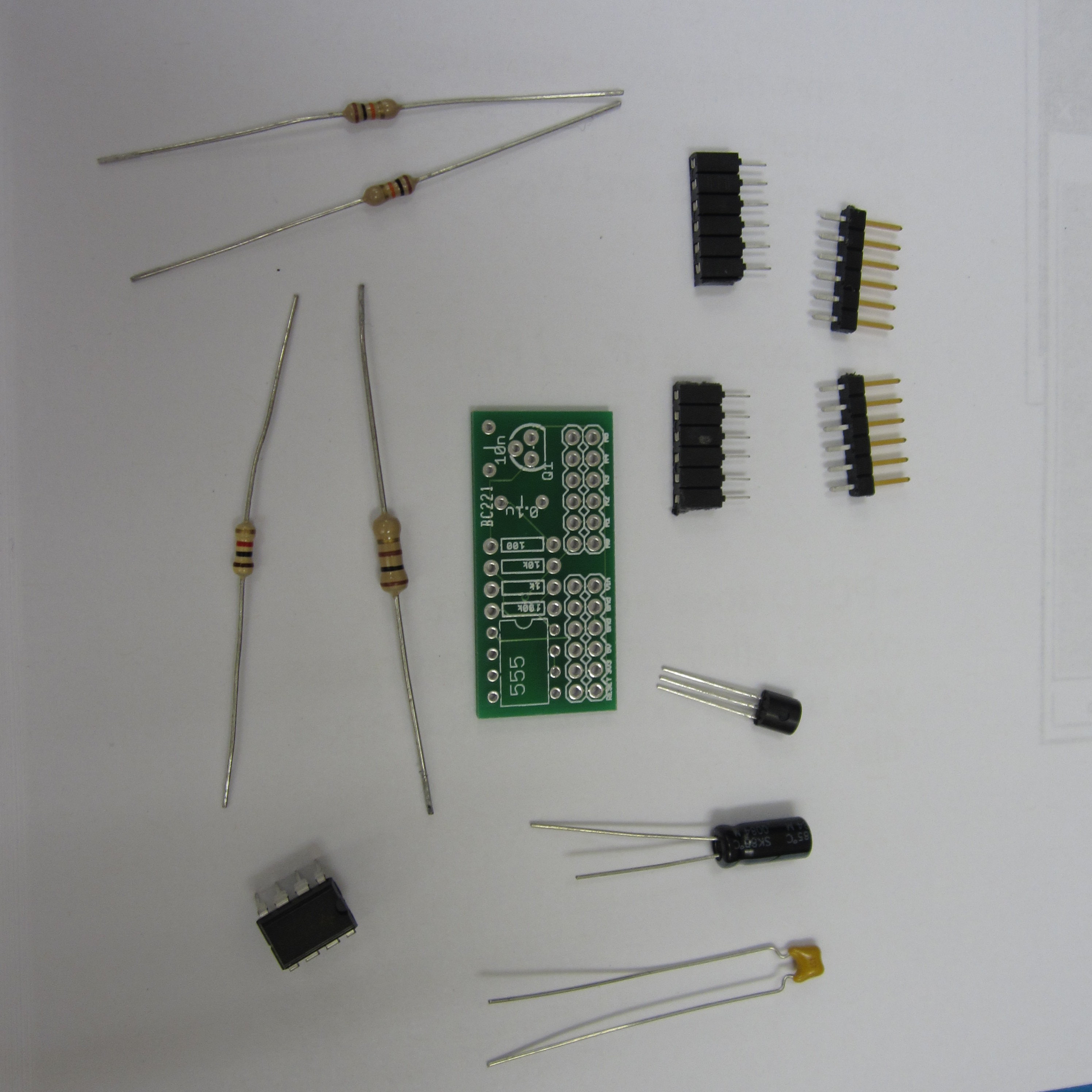
1. Gather Parts
Make sure you have all the parts listed in the parts list. The parts in this project don't exactly match the parts printed on the PCB. The parts printed on the PCB can be used, but they look different than the parts used in these instructions.
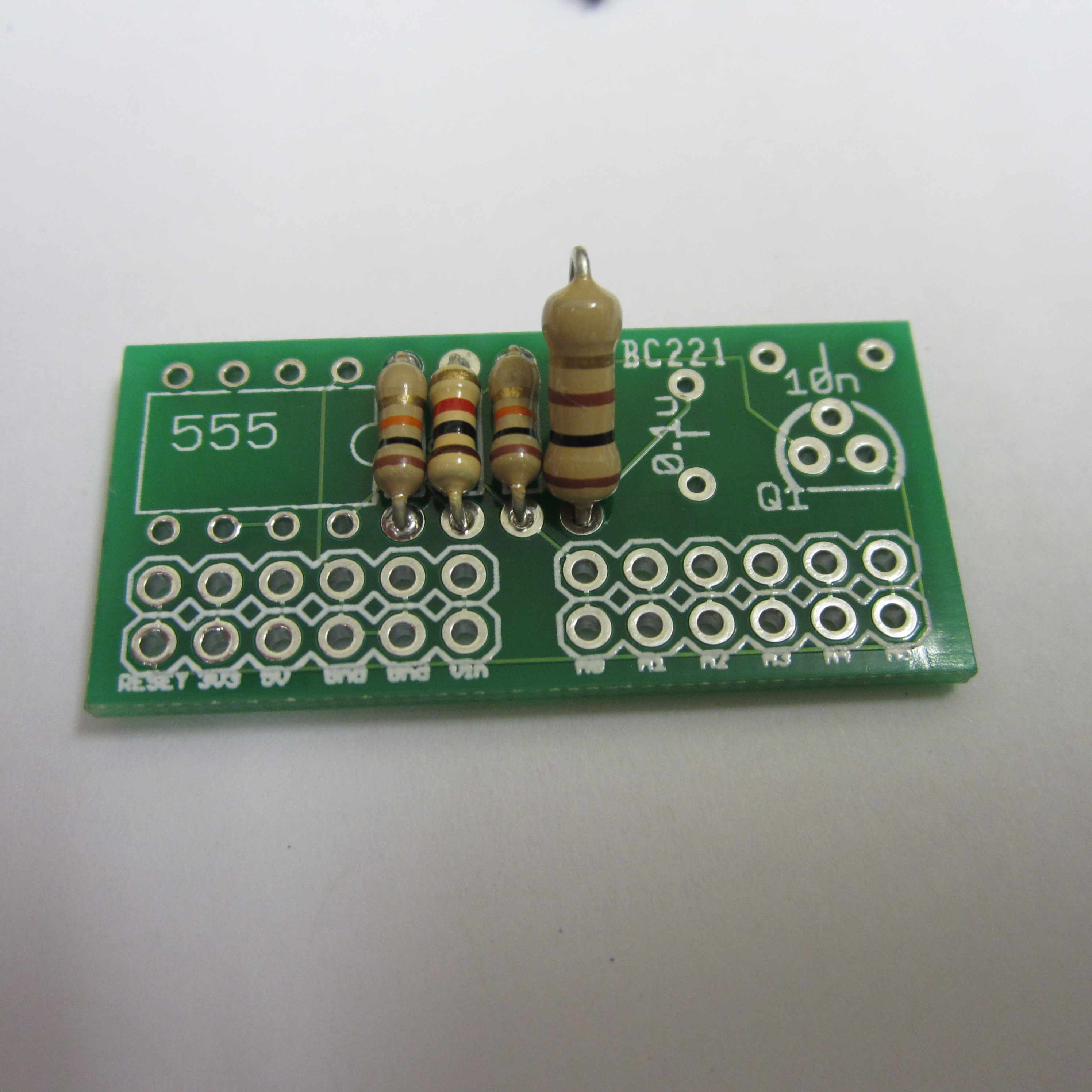
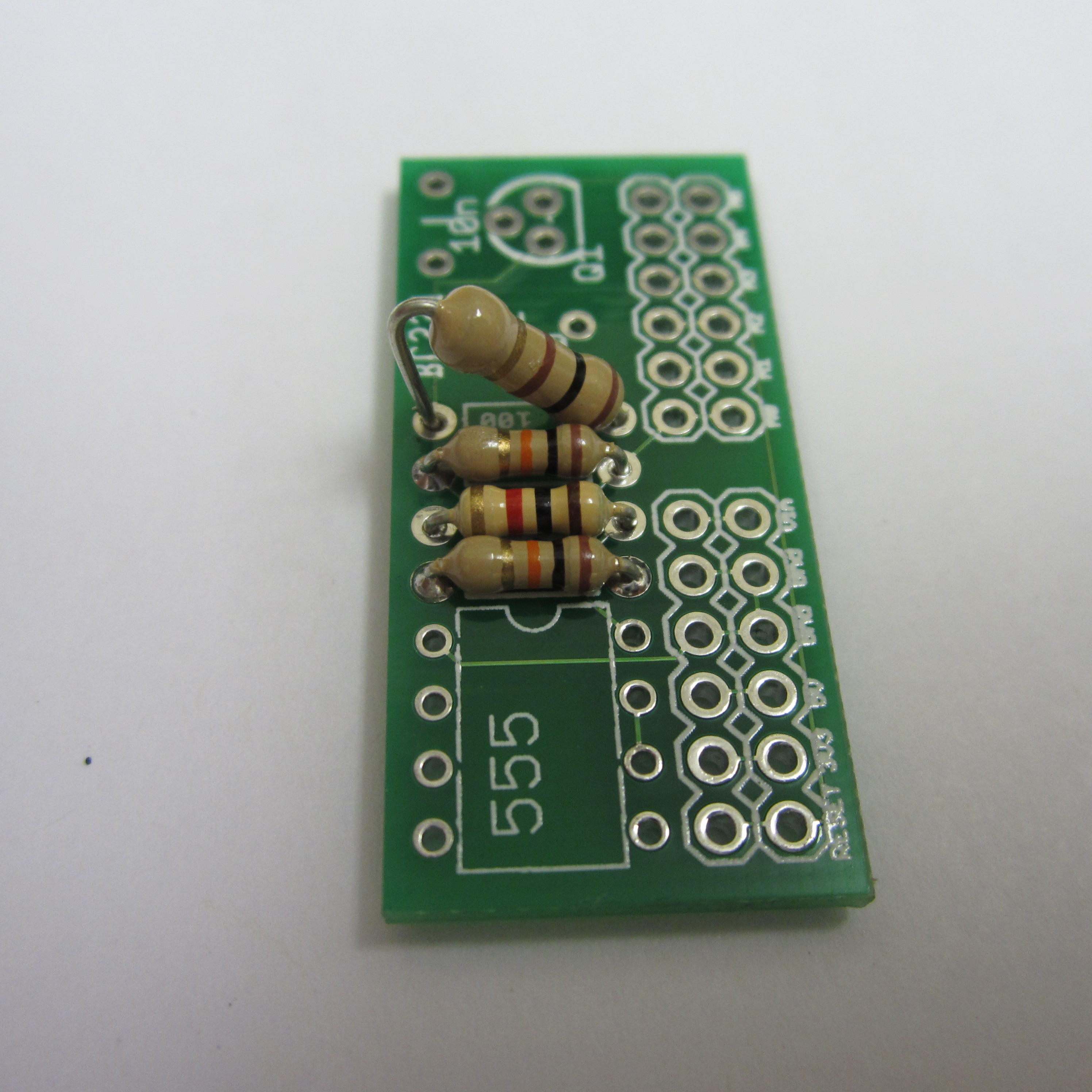
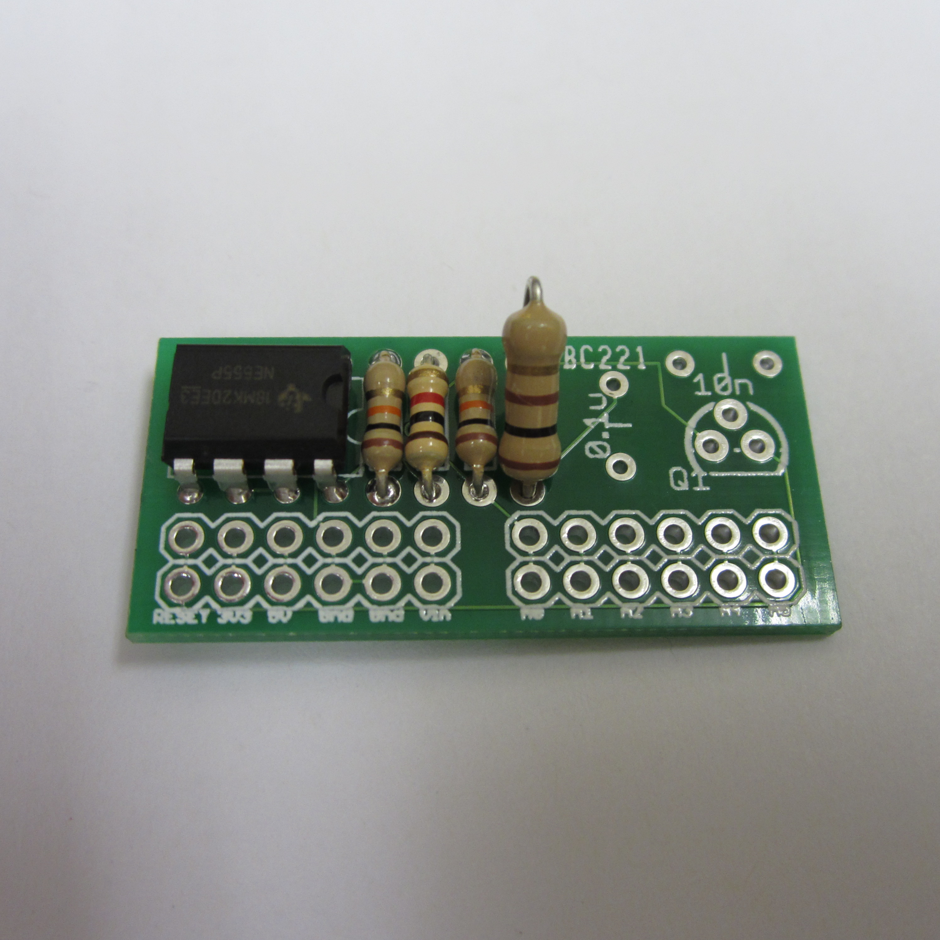
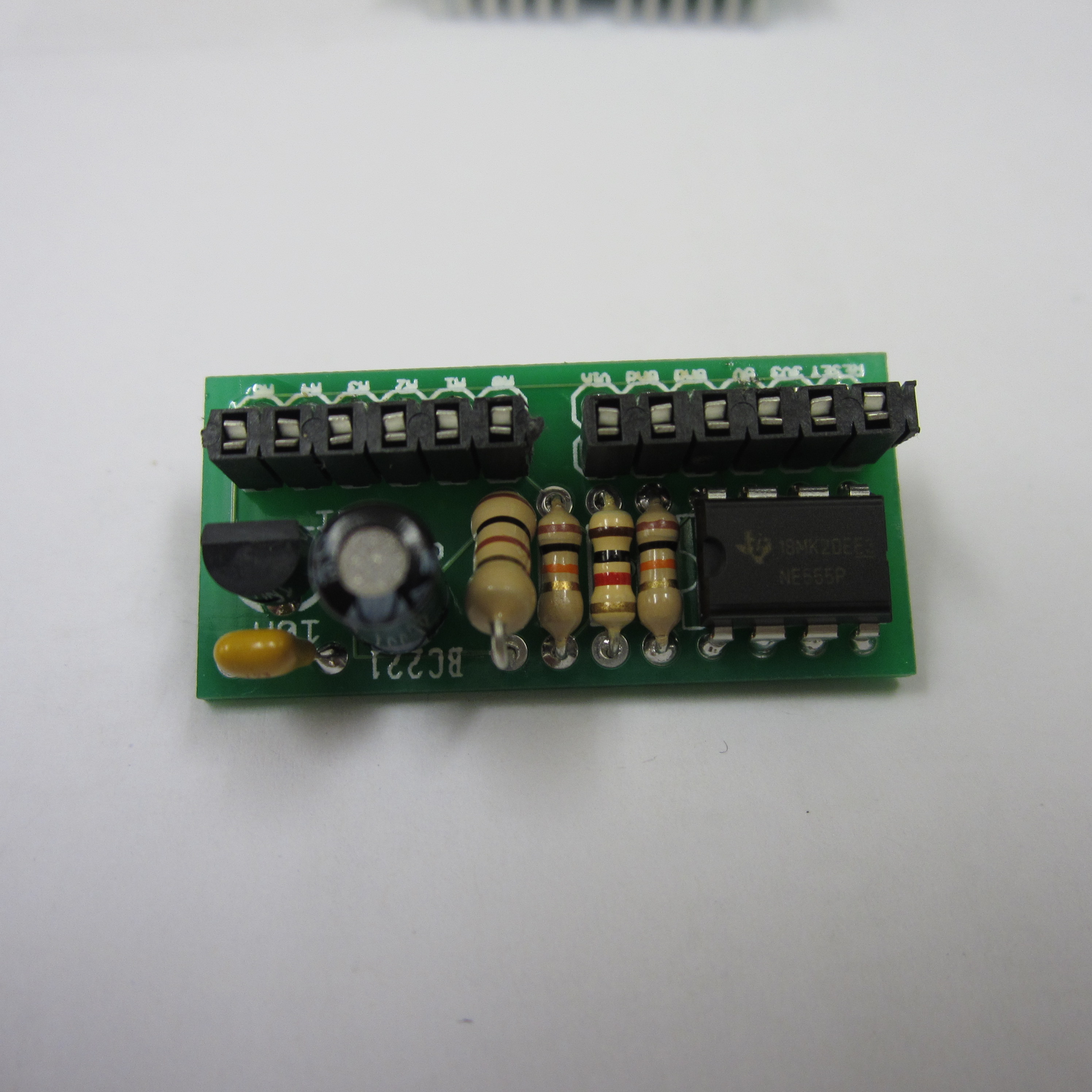
2. Solder Resistors
Solder the resistors in place as shown. From left-to-right, the resistors are 10k, 1k, 10k, and 100 ohm. You could also use resistors and capacitors that have the same values as what is printed on the PCB. (The last resistor is propped up funny because I used a larger resistor than the PCB was designed to hold. This won't affect the device's performance.)
3. Solder 555 Timer
Solder the 555 timer and make sure that the dimple on the top of the IC goes to the right just like the outline on the PCB.
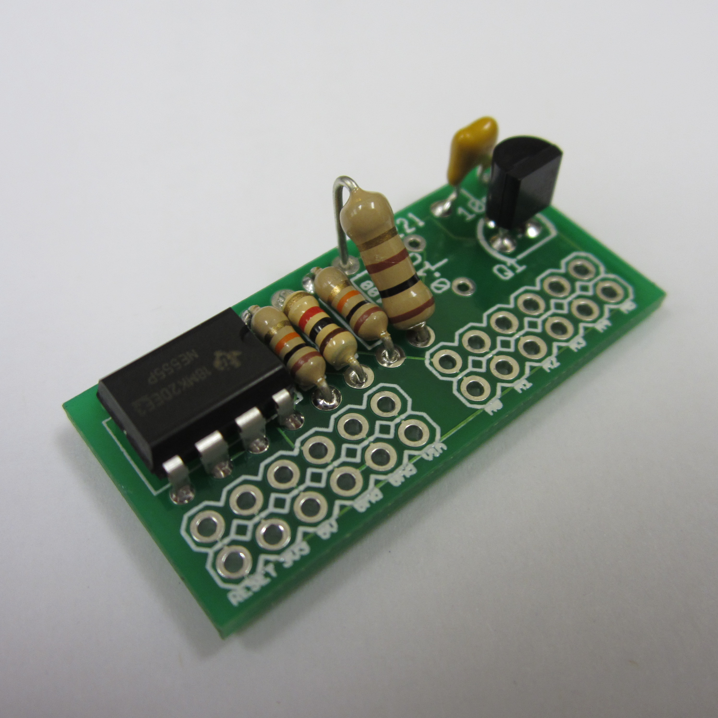
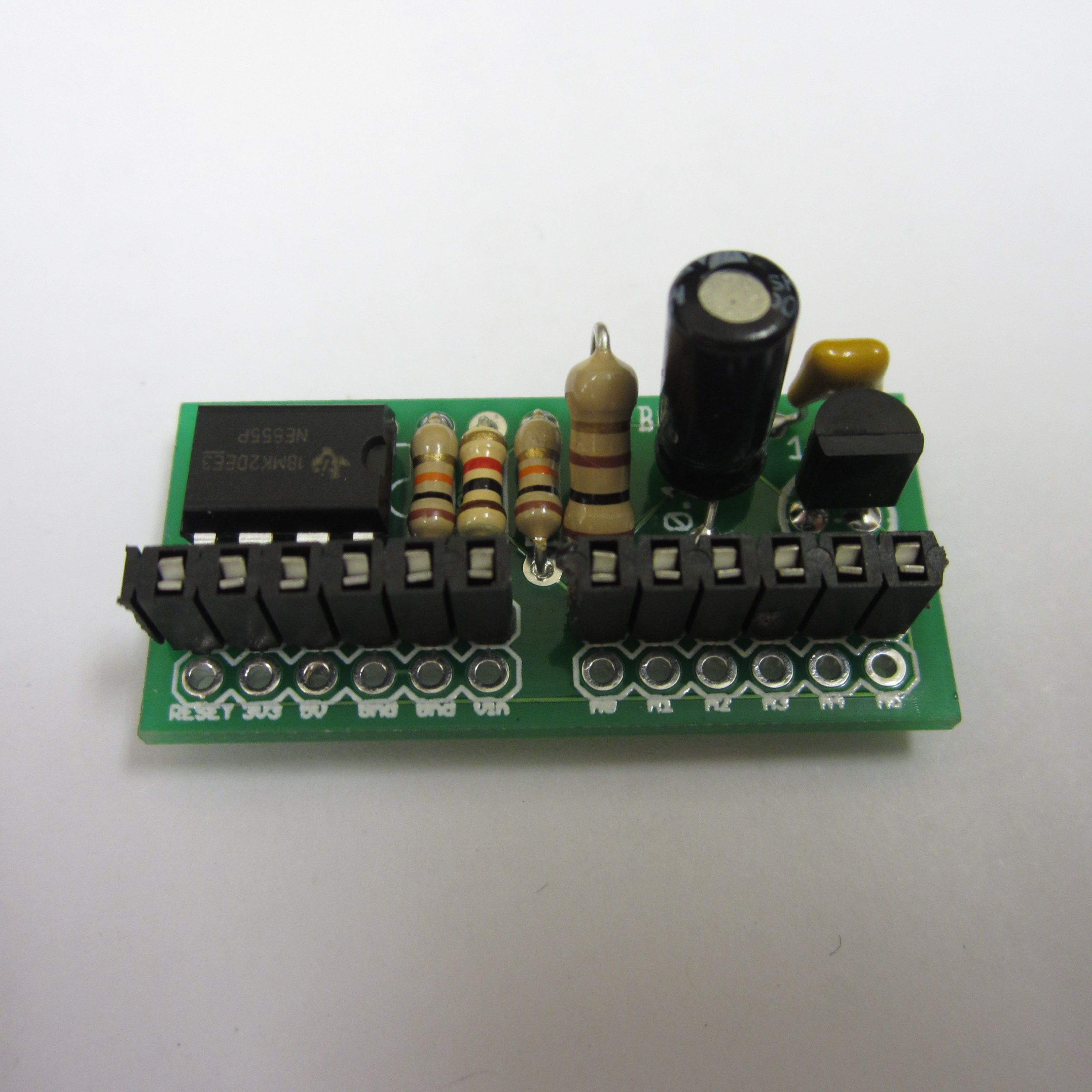
4. Solder Transistor
Solder the transistor as shown. The outline on the PCB should match up with the outline of the physical device as shown.

5. Solder 0.01uF Capacitor
Solder the 0.01uF (aka 10nF) capacitor in the slot labeled 10nF. The polarity of this capacitor doesn't matter.
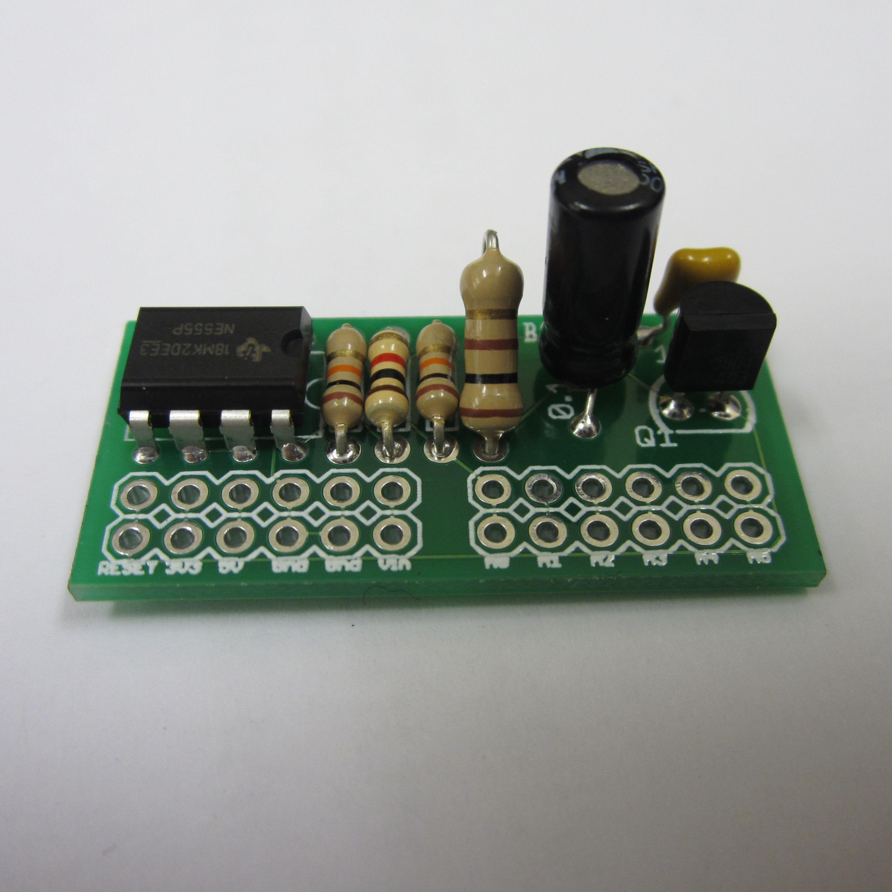
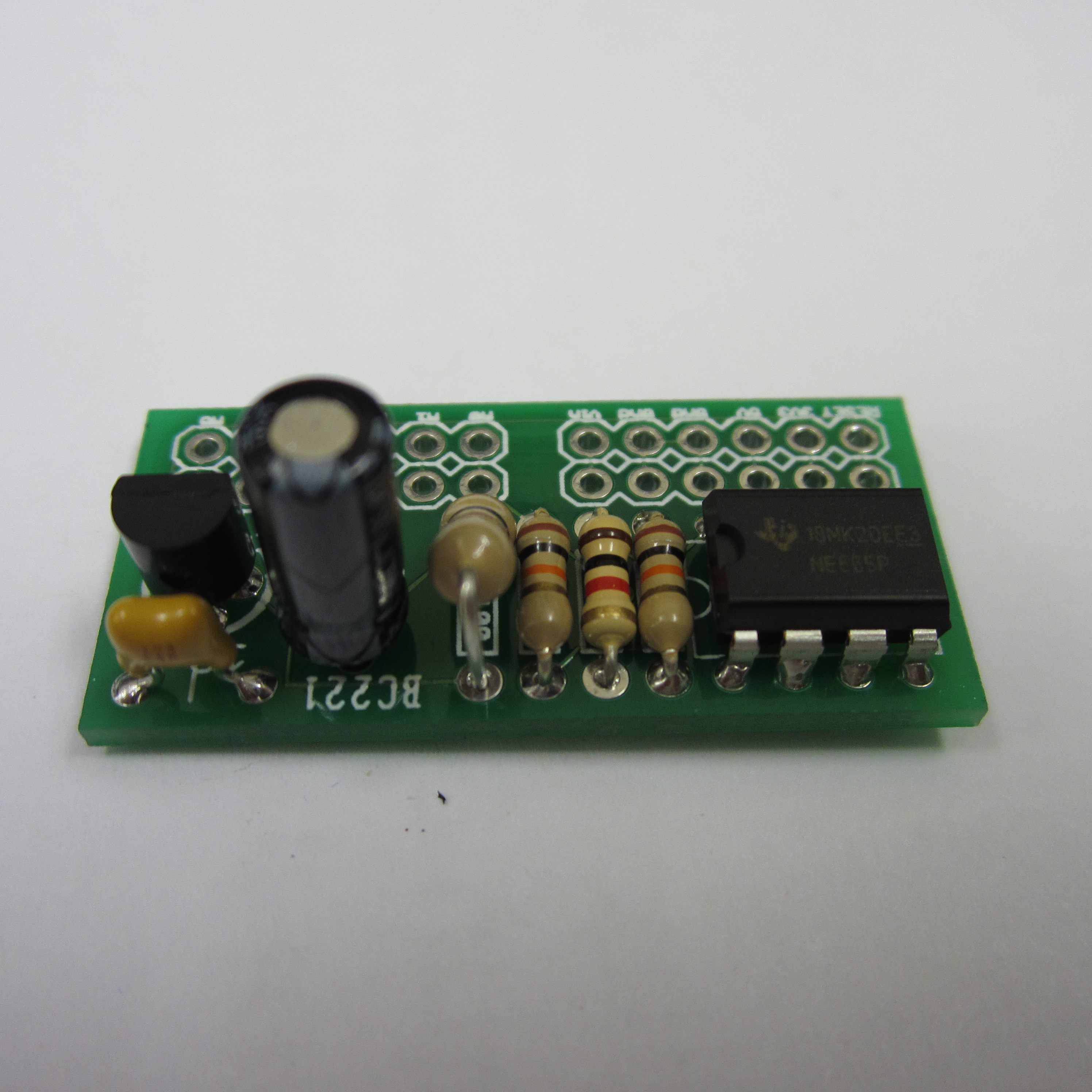
6. Solder 4.7uF Capacitor
Solder the 4.7uF cappacitor in the slot labeled 0.1uF. Make sure the stripe on the side of the capacitor is near the board edge.
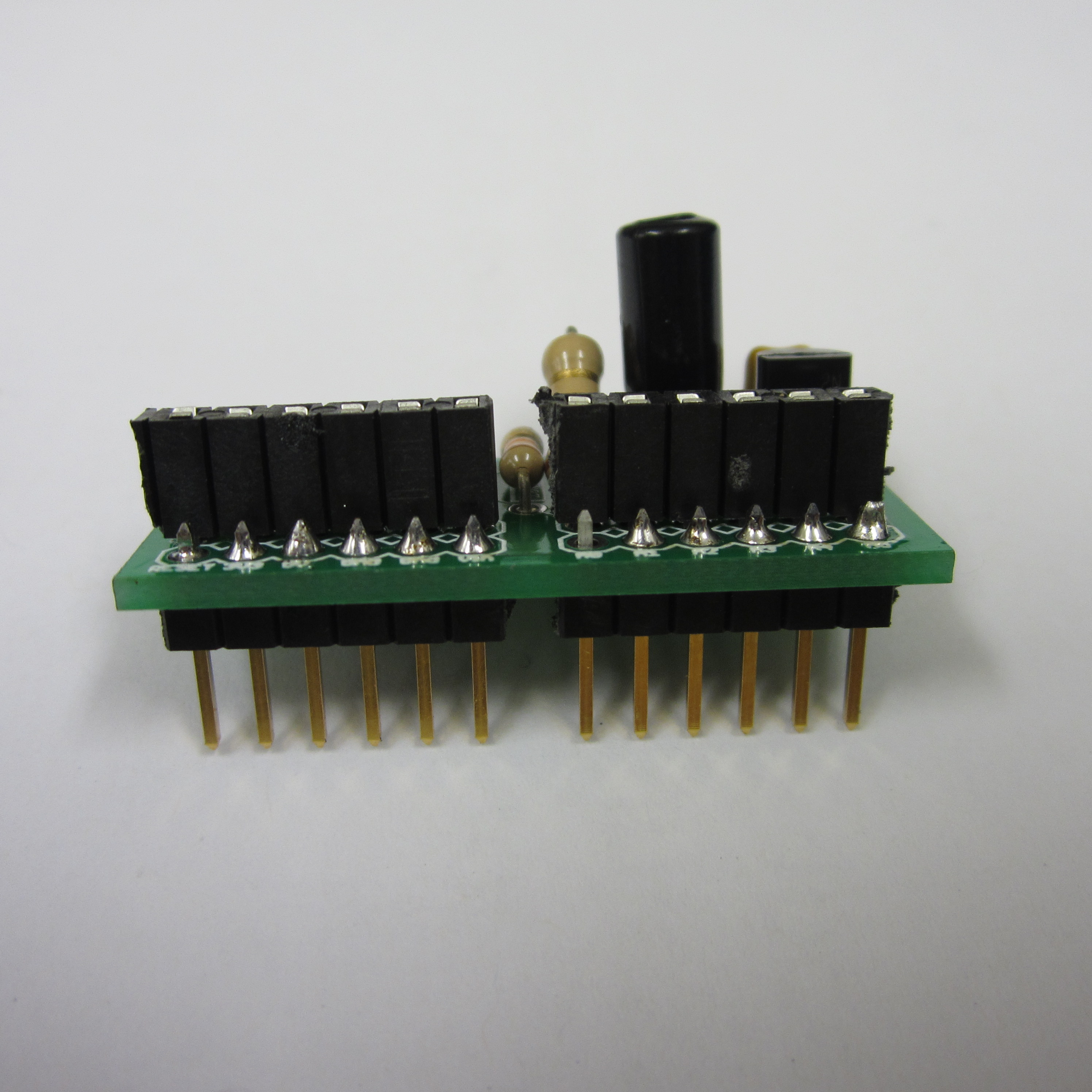
7. Solder the Female Headers
Be careful when breaking the female headers apart. It is easy to break them in the wrong position if you are not careful. I used a pair of needle-nose pliers to break the headers apart.
8. Solder the Male Headers
The male headers point down so they can be inserted into the female headers on the Arduino.
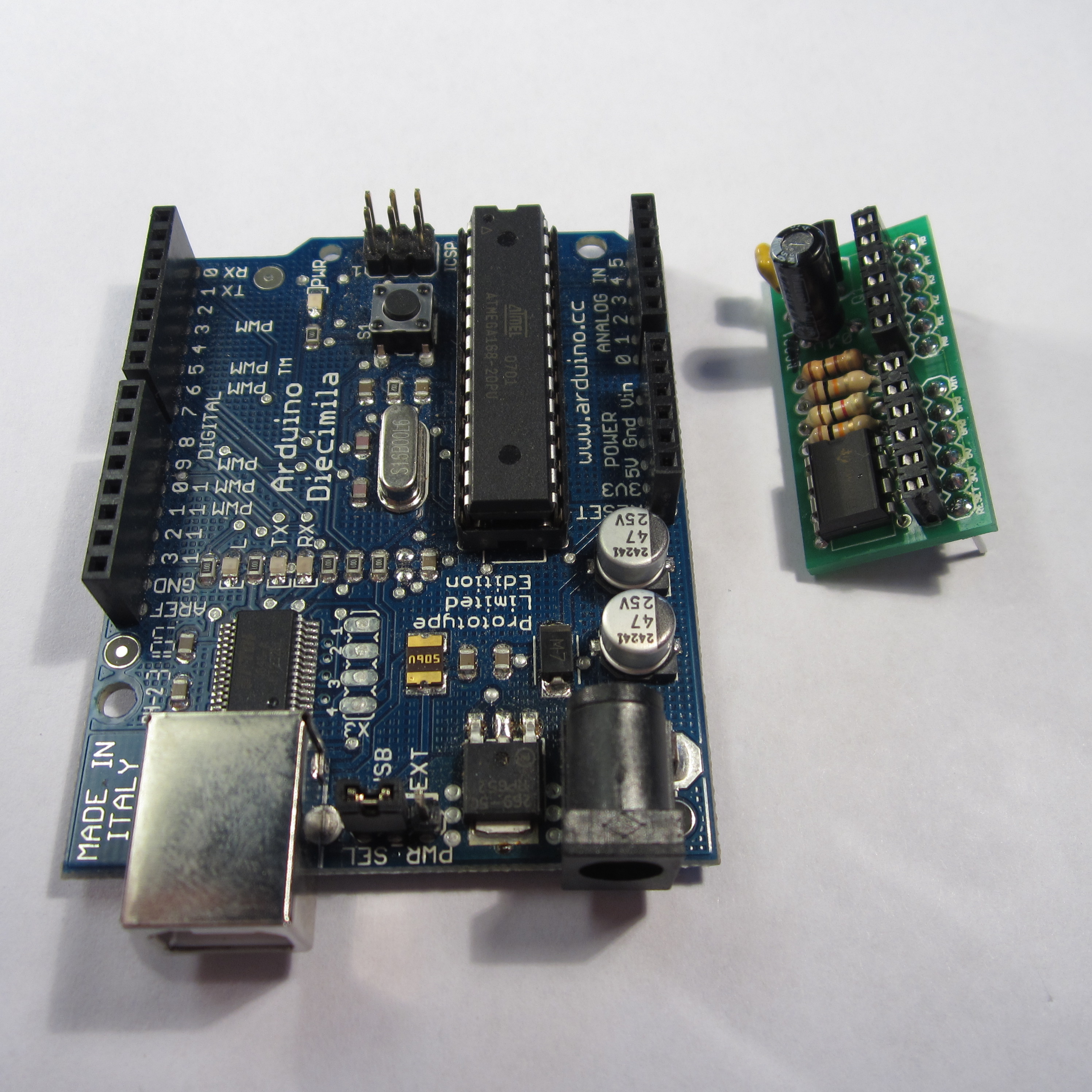
9. Use it!
Plug the Arduino Reset Board into your Arduino. To test to make sure it works, upload the Arduino_Reset_Sketch to your Arduino. The LED on board the Arduino should turn on for 5 seconds, then turn off for one second, and repeat this cycle if the board is working correctly. Watch the video in the description at the top of this page to see what this looks like on my Arduino.
Special note: In custom applications, make sure that the first three lines of code in setup() your Arduino sketch are as follows:
digitalWrite(A0, LOW);
pinMode(A0, OUTPUT);
digitalWrite(A0, LOW);
Failure to do so may result in your Arduino getting stuck in a reset loop.

Download steps w/o images
Download steps w/ images
Revisions
1 - Initial project release
Add revision
blog comments powered by Disqus
Back


