-
Featured User: kurt

Open-source hardware project hosting is my passion. I spend most of my free time building neat gadgets or planning what I'll build next. I love building things, and I want to make Open Hardware Hub a place that inspires others to build, ...
-
Updates 2013 February 18
It's been a while, hasn't it? Well, that's ok because we've got a lot of updates to talk about. Most of these have been effective on the site fora couple weeks now. A few may or may not be active when this article gets posted, but they'll certainly be applied in the ...
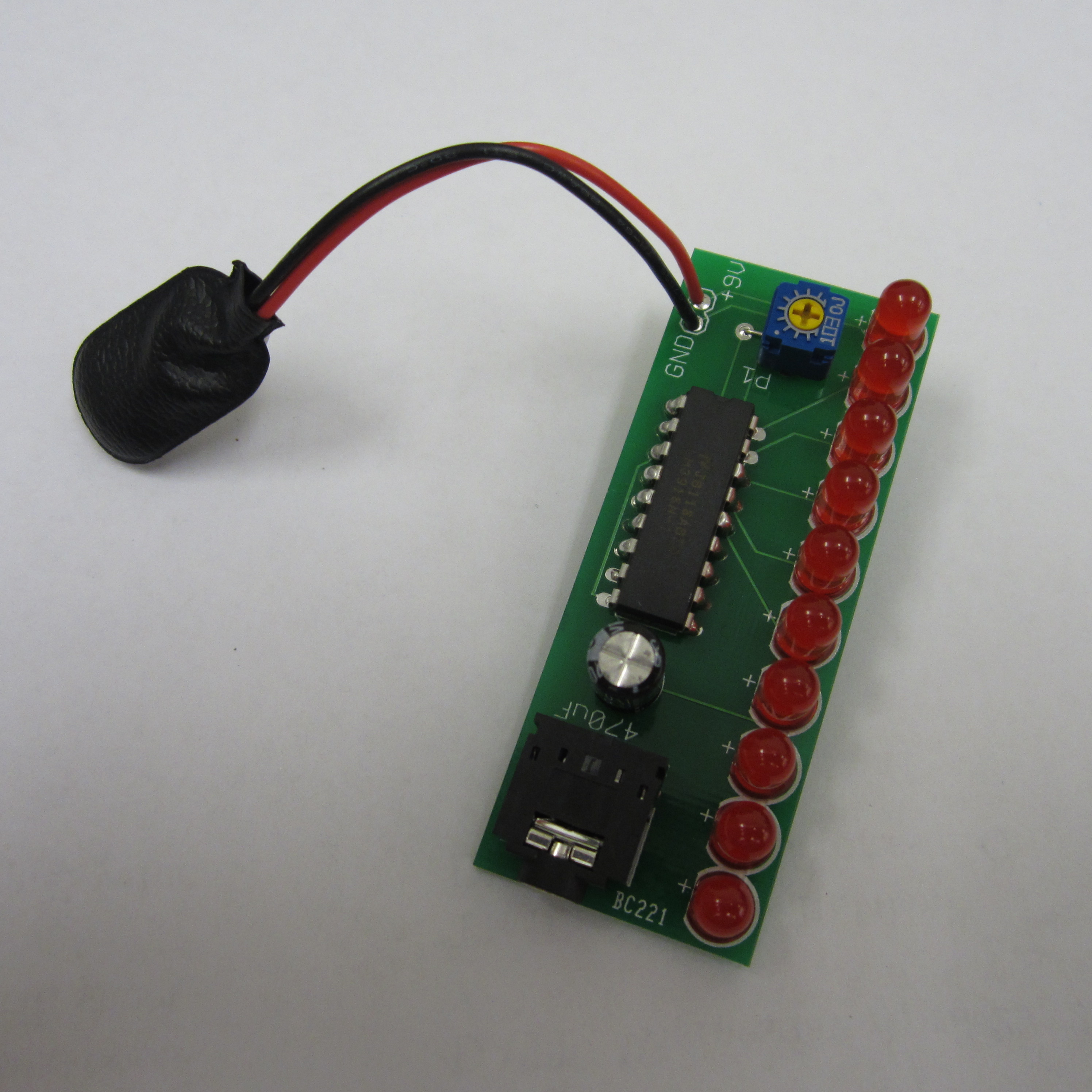
Mono VU Meter PCB
Files
- VU Meter V1.zip - VU Meter GERBER
- VU Meter.sch - VU Meter EAGLE Schematic
- VU Meter.brd - VU Meter EAGLE Board
Bill of Materials
| Qty | Part # | Description | Schematic ID | Source | |
|---|---|---|---|---|---|
| 1 |
|
SJ1-3524NG | CONN JACK STEREO R/A 4PIN 3.5MM | J1 | Source |
| 1 |
|
LM3916N-1 | LED BAR GRAPH DRIVER, 3916, DIP18 | IC1 | Source |
| 1 |
|
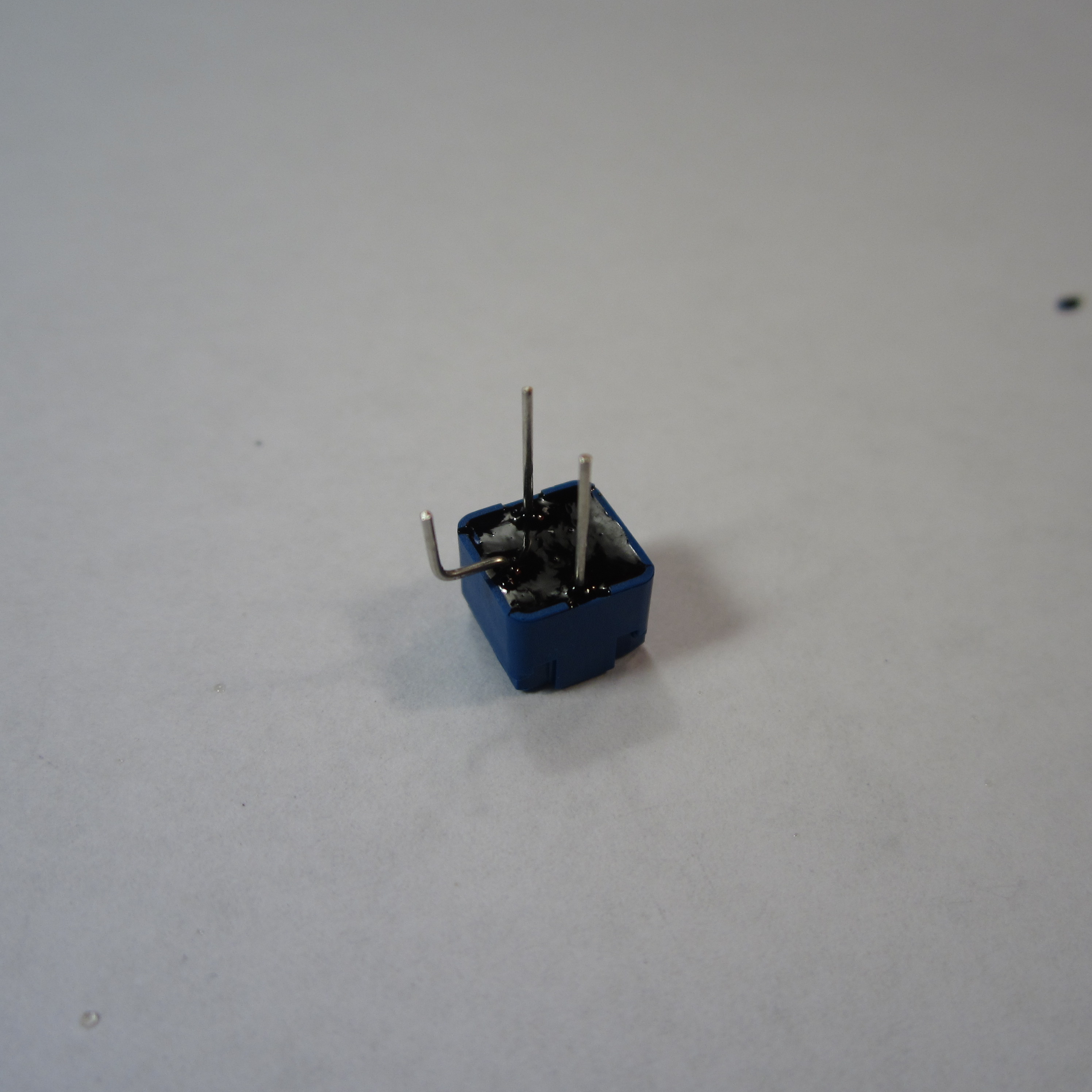
CT6EP103 | TRIMMER 10K OHM 0.5W TH | P1 | Source |
| 1 |
|
UVR1A471MED | CAPACITOR ALUM ELECT 470UF, 10V, RADIAL | C1 | Source |
| 1 |
|
BS6I | SNAPS 9V 6" LEADS I-STYLE | JP1 | Source |
| 10 |
|
WP7113LID | 5MM LOW CURRENT RED LED, LAMP THOLE, BULK | LED1-10 | Source |
Download BOM w/o images
Download BOM w/ images
Steps
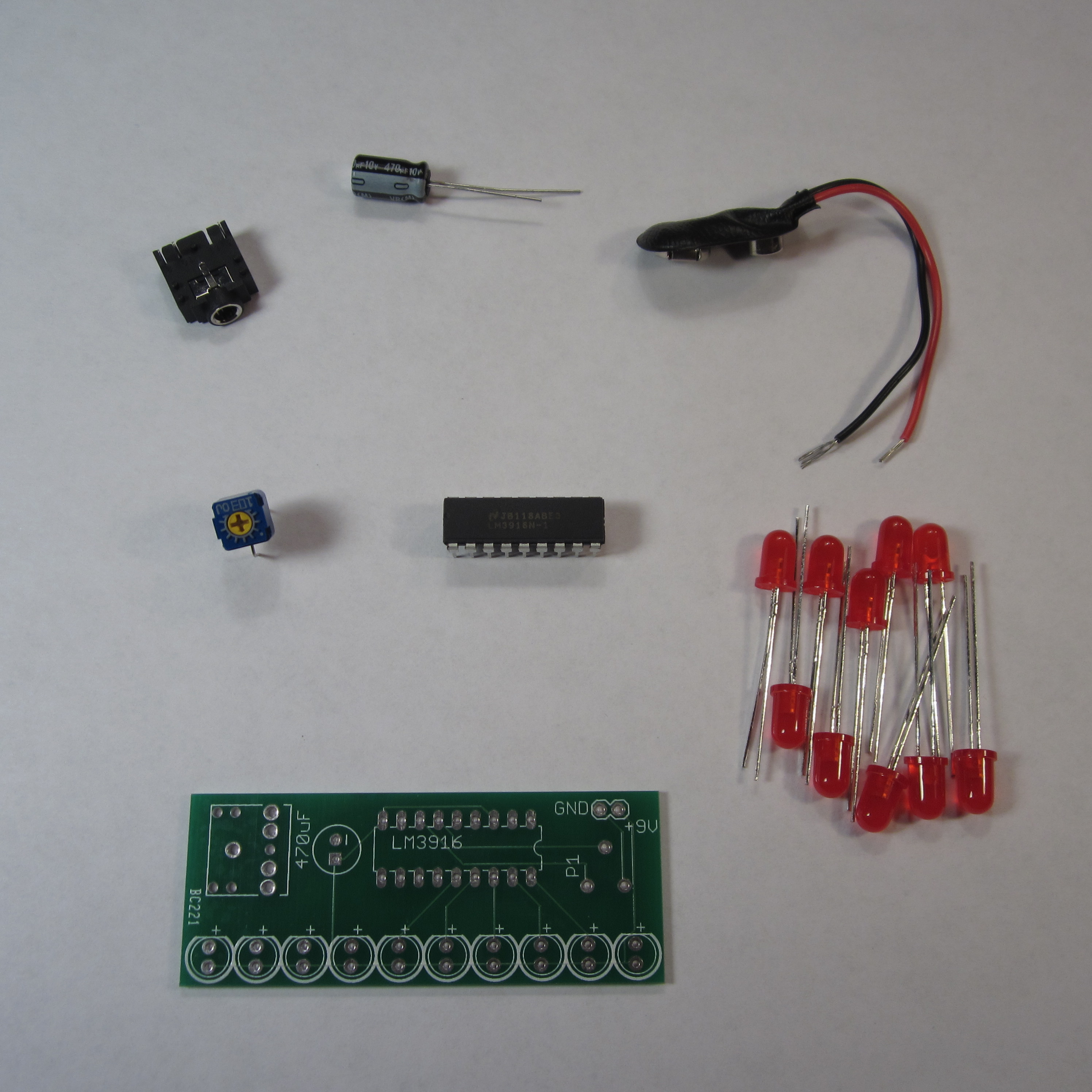
1. Gather Parts
You'll need 10 LEDs, an electrolytic capacitor (the size isn't critical, but 470uF is recommended), an LM3916, a 10k potentiometer, a 9V battery, a 9V battery clip, and the VU Meter PCB (printed circuit board).
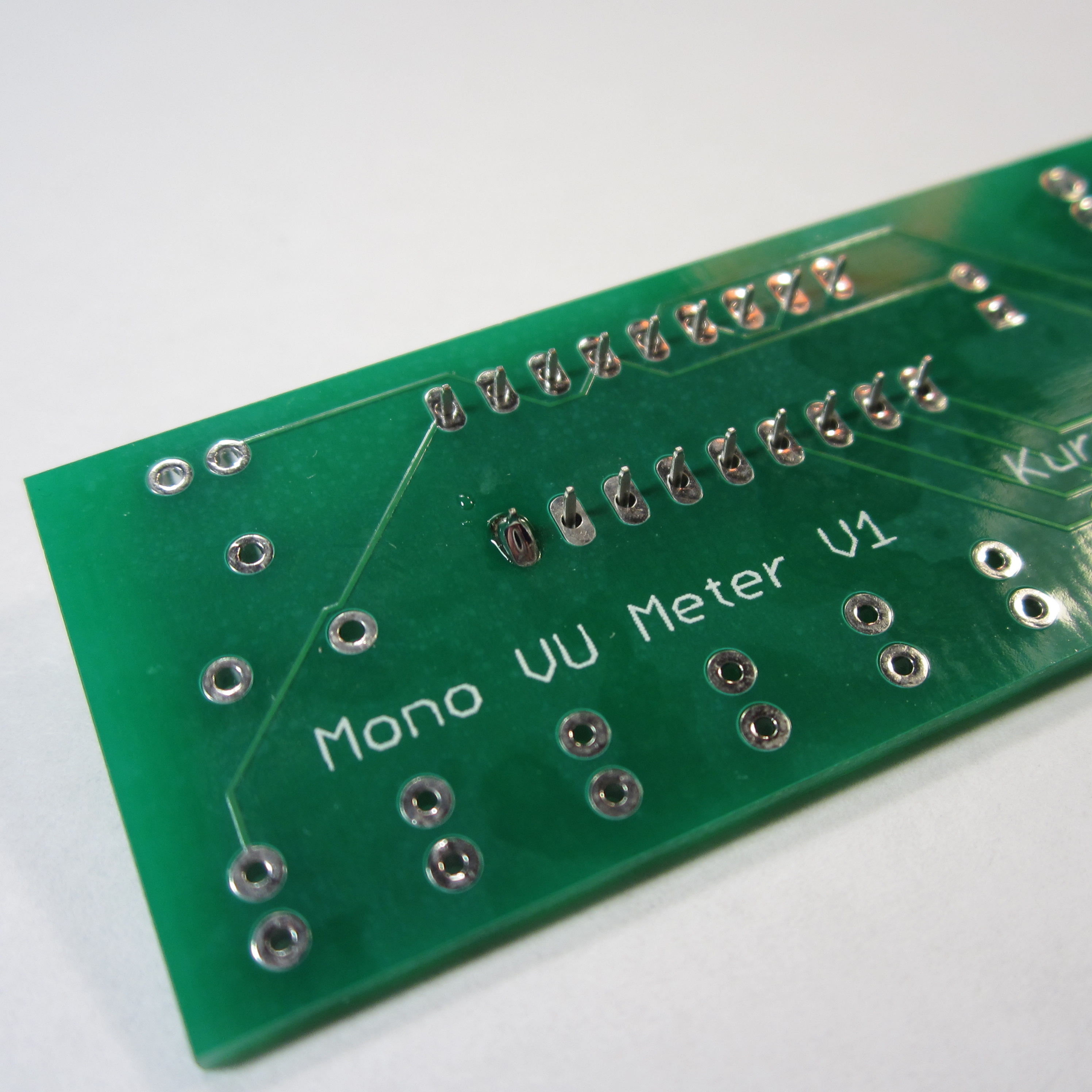
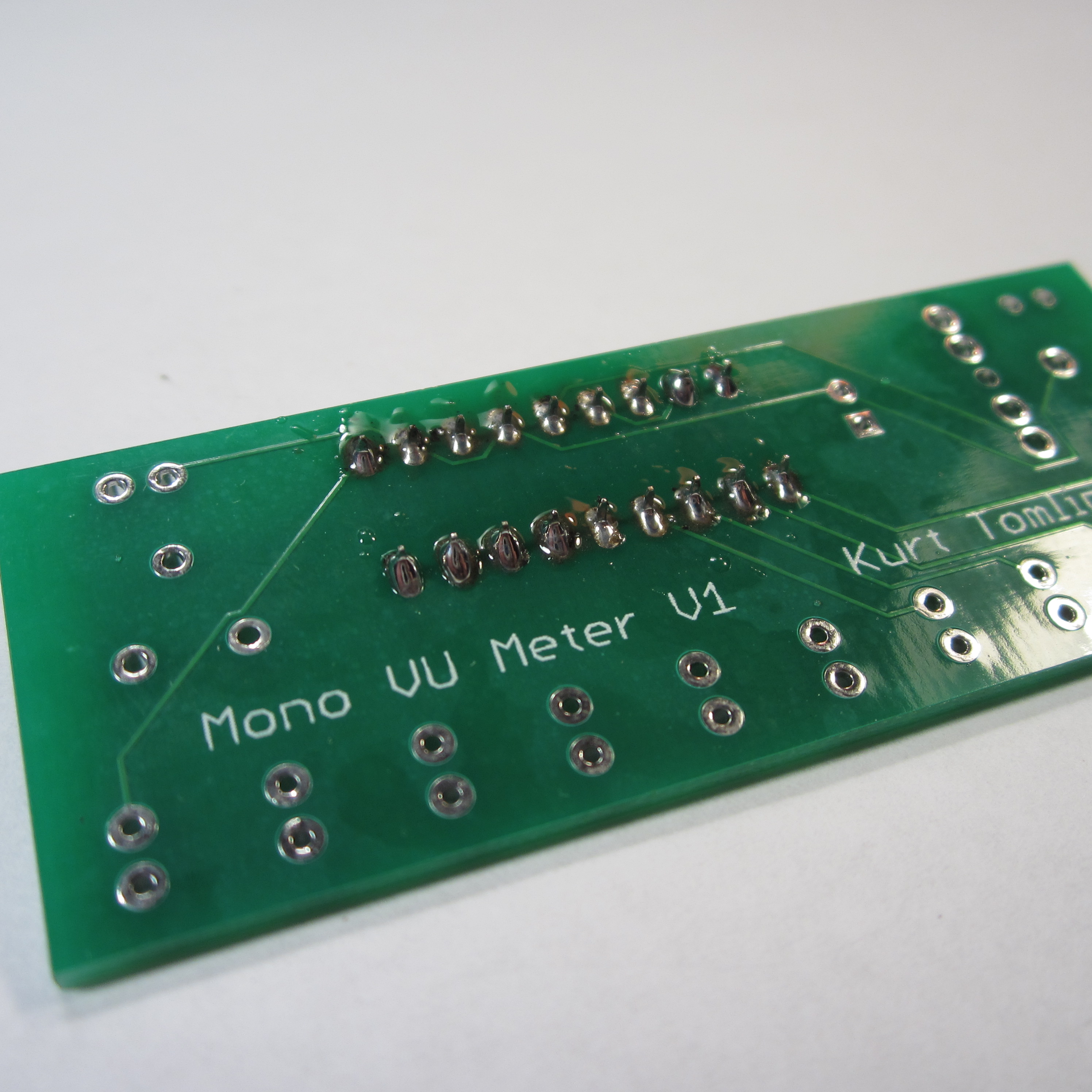
You can get the PCB by going to BatchPCB and submitting the GERBER files above for processing.
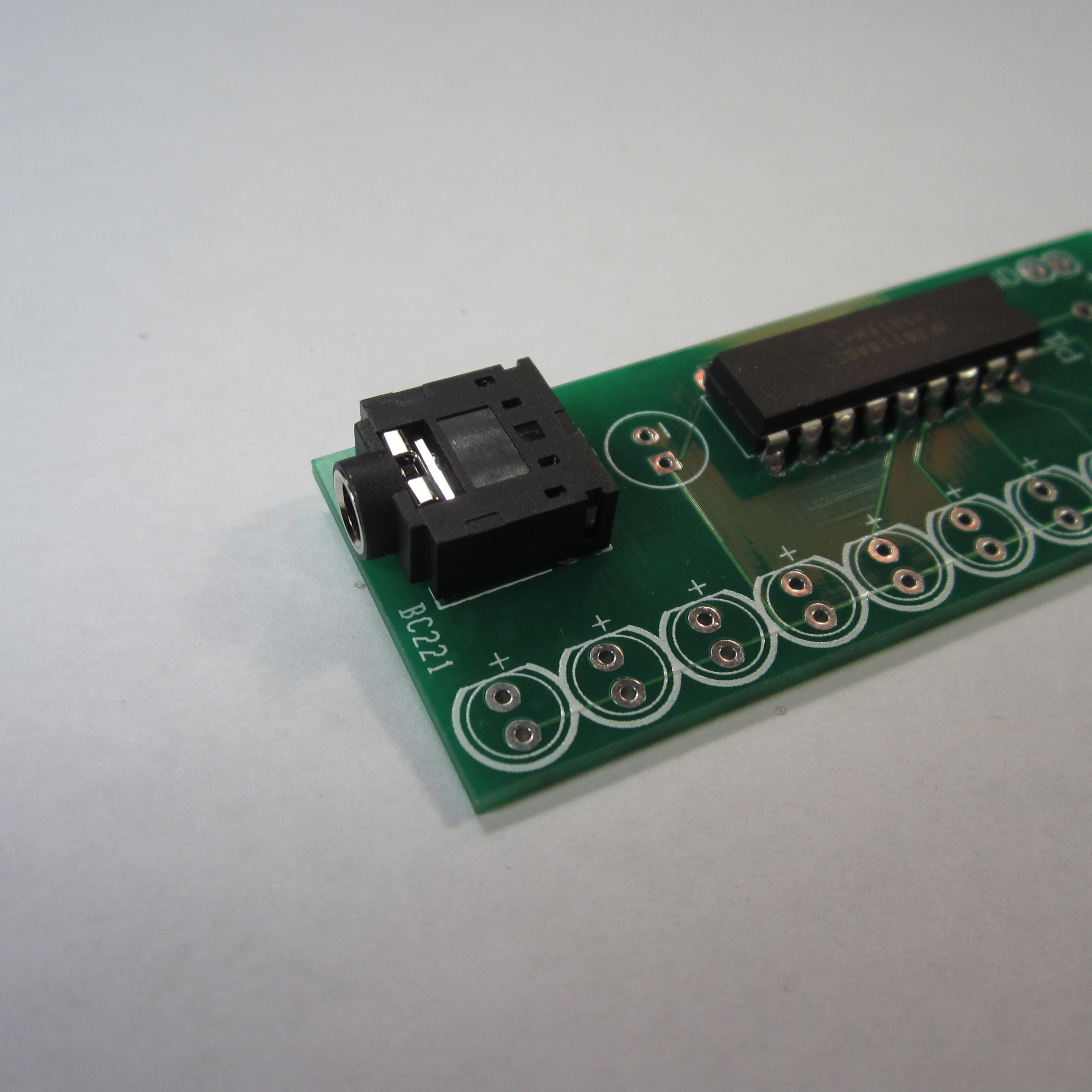
2. Solder IC1
Insert the LM3916 as shown. Make sure to line up the dimple on the IC with the artwork on the PCB.
Solder on leg of the IC. Then, push the IC into place while re-melting the solder on that one leg. The solder on that leg will hold the IC in place while you solder the rest of the IC's legs.

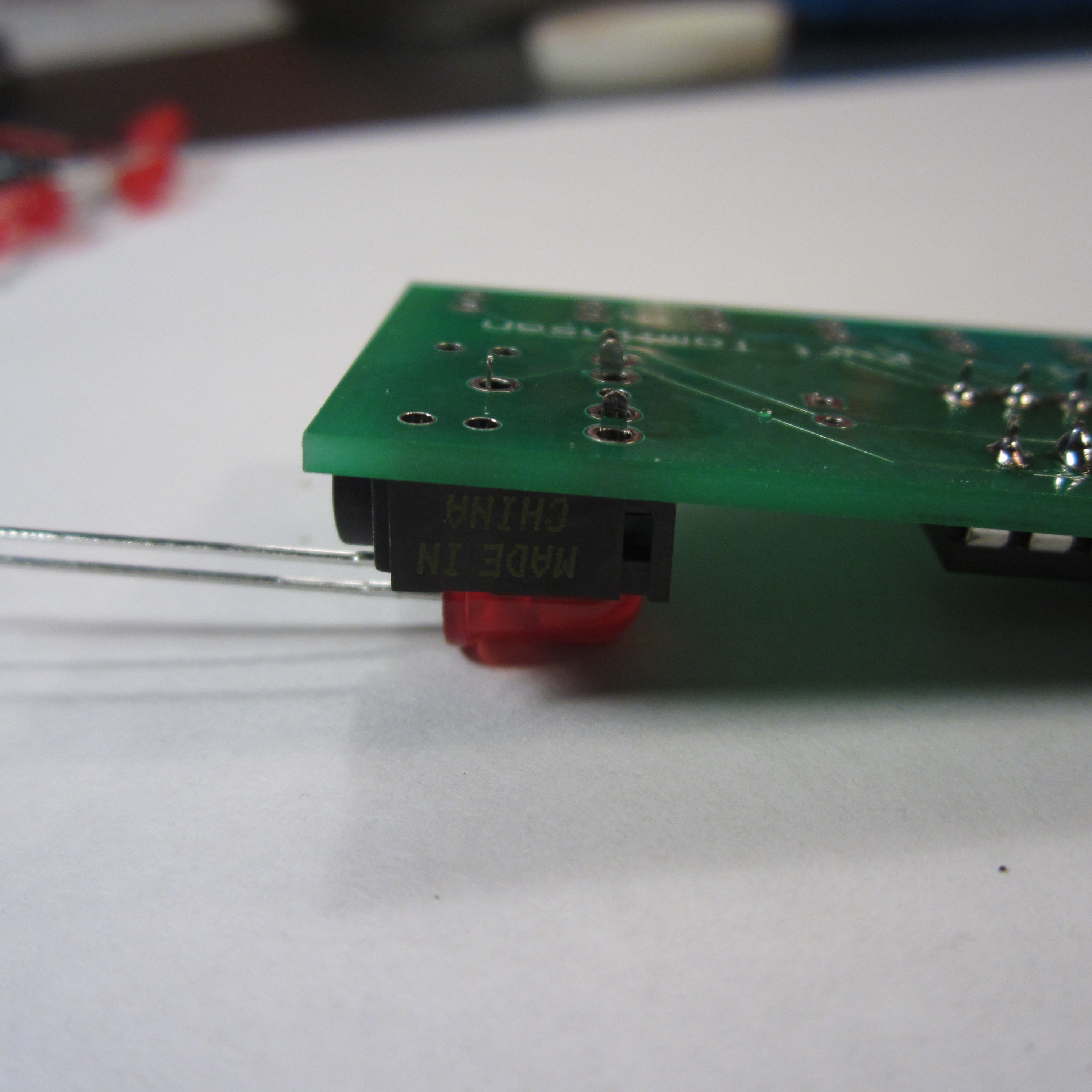
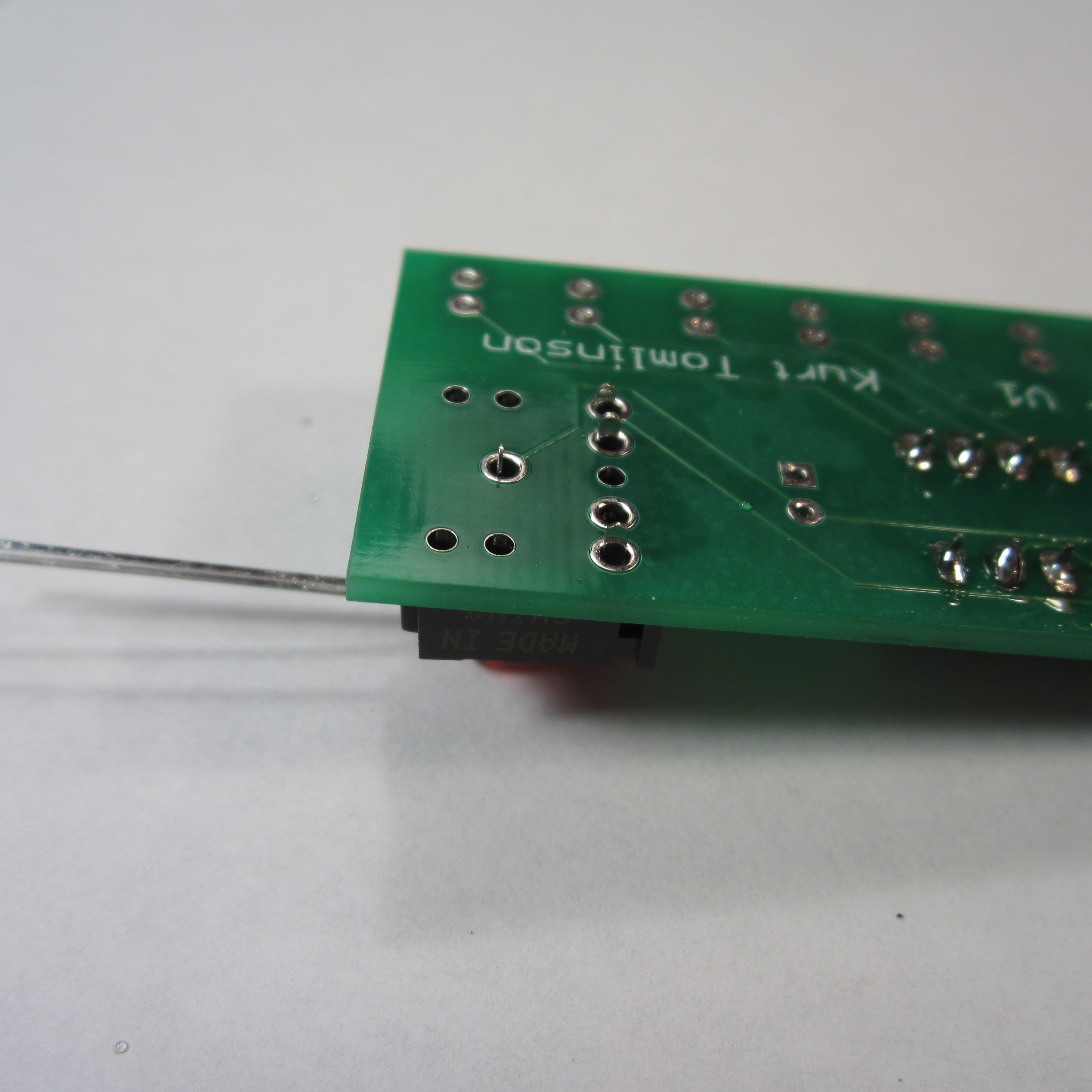
3. Solder Audio Jack
I used an LED to prop up the audio jack so that it stayed in the board while I soldered the first leg. I then finished soldering it the same way as the IC in the last step.
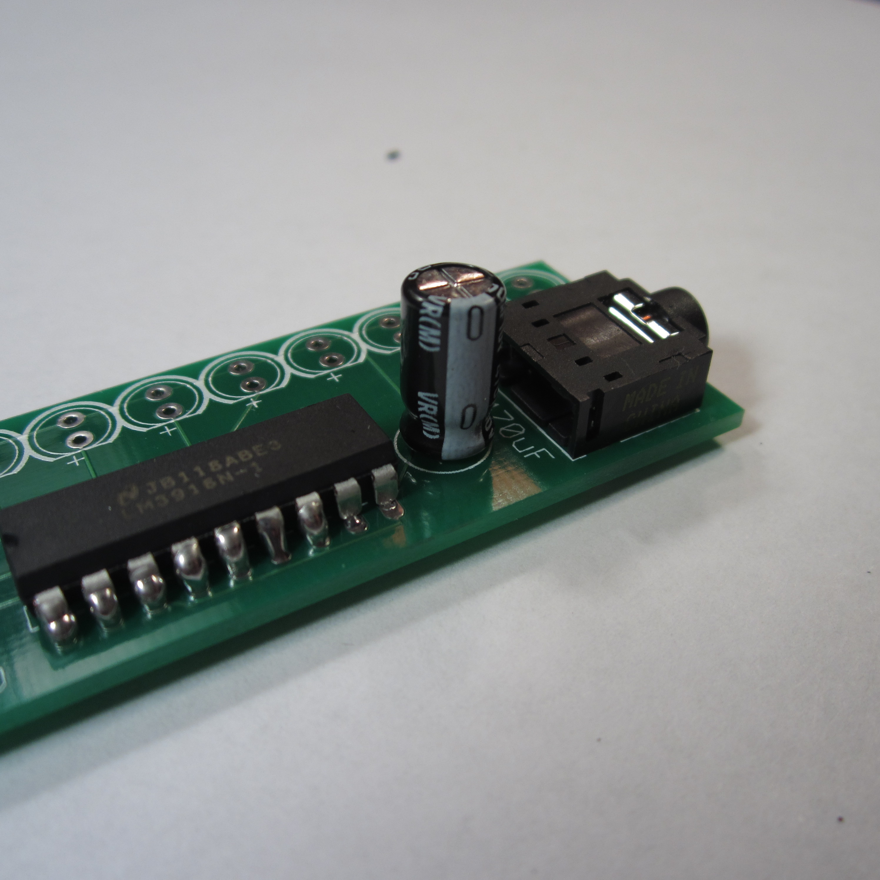
4. Solder Capacitor
Insert the capacitor in the position between the IC and the audio jack. Make sure that the stripe on the side of the capacitor is on the same side as the minus sign on the PCB artwork.
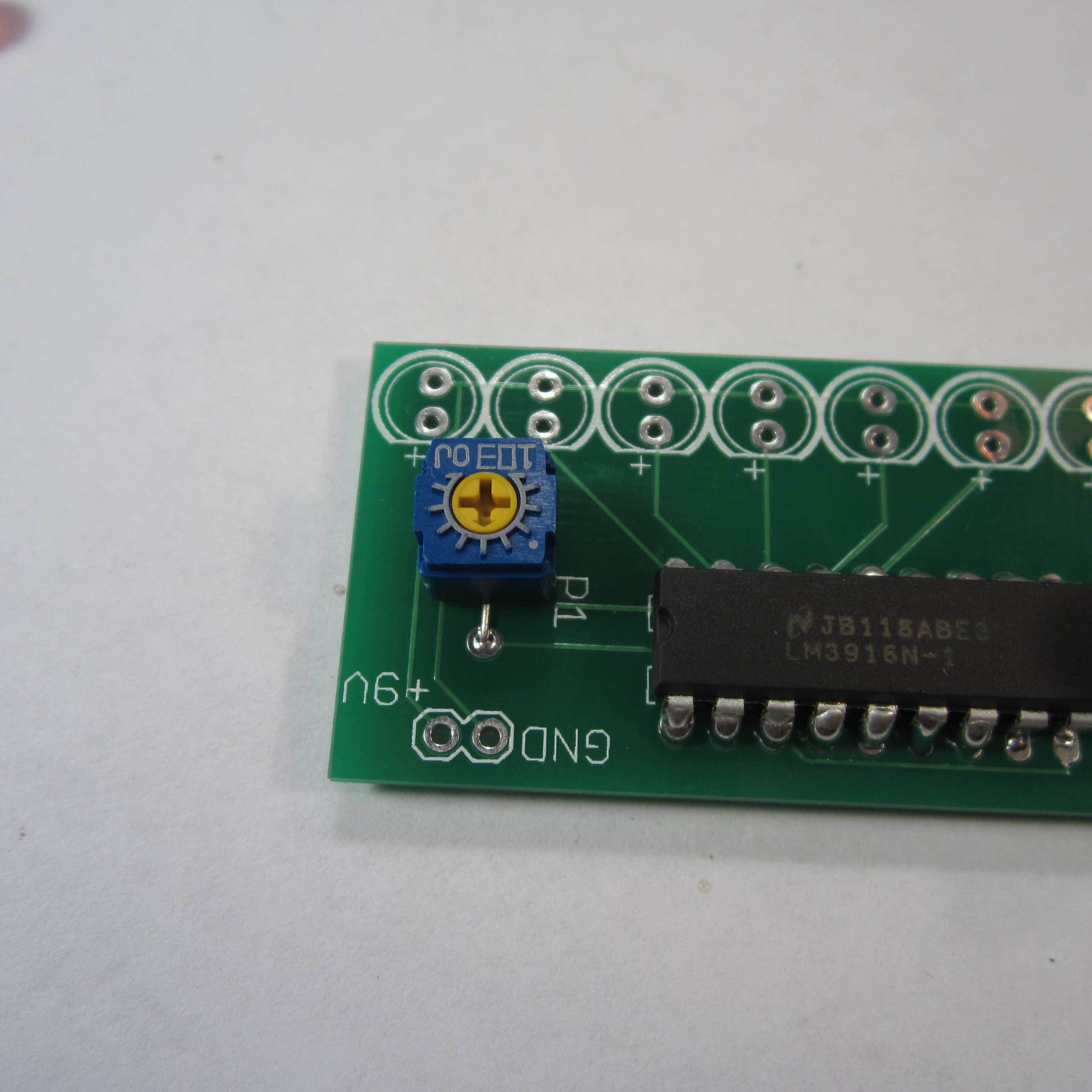
5. Solder Potentiometer
Solder the potentiometer in place. The footprint of the pot is not quite the same as that on the PCB, so you will have to bend one leg of the pot to make it fit. Alternately, you can buy a different pot that fits the holes on the PCB.
Download steps w/o images
Download steps w/ images
Revisions
2 - added youtube link
1 - Initial project release
Add revision
blog comments powered by Disqus
Back


