-
Featured User: kurt

Open-source hardware project hosting is my passion. I spend most of my free time building neat gadgets or planning what I'll build next. I love building things, and I want to make Open Hardware Hub a place that inspires others to build, ...
-
Updates 2013 February 18
It's been a while, hasn't it? Well, that's ok because we've got a lot of updates to talk about. Most of these have been effective on the site fora couple weeks now. A few may or may not be active when this article gets posted, but they'll certainly be applied in the ...
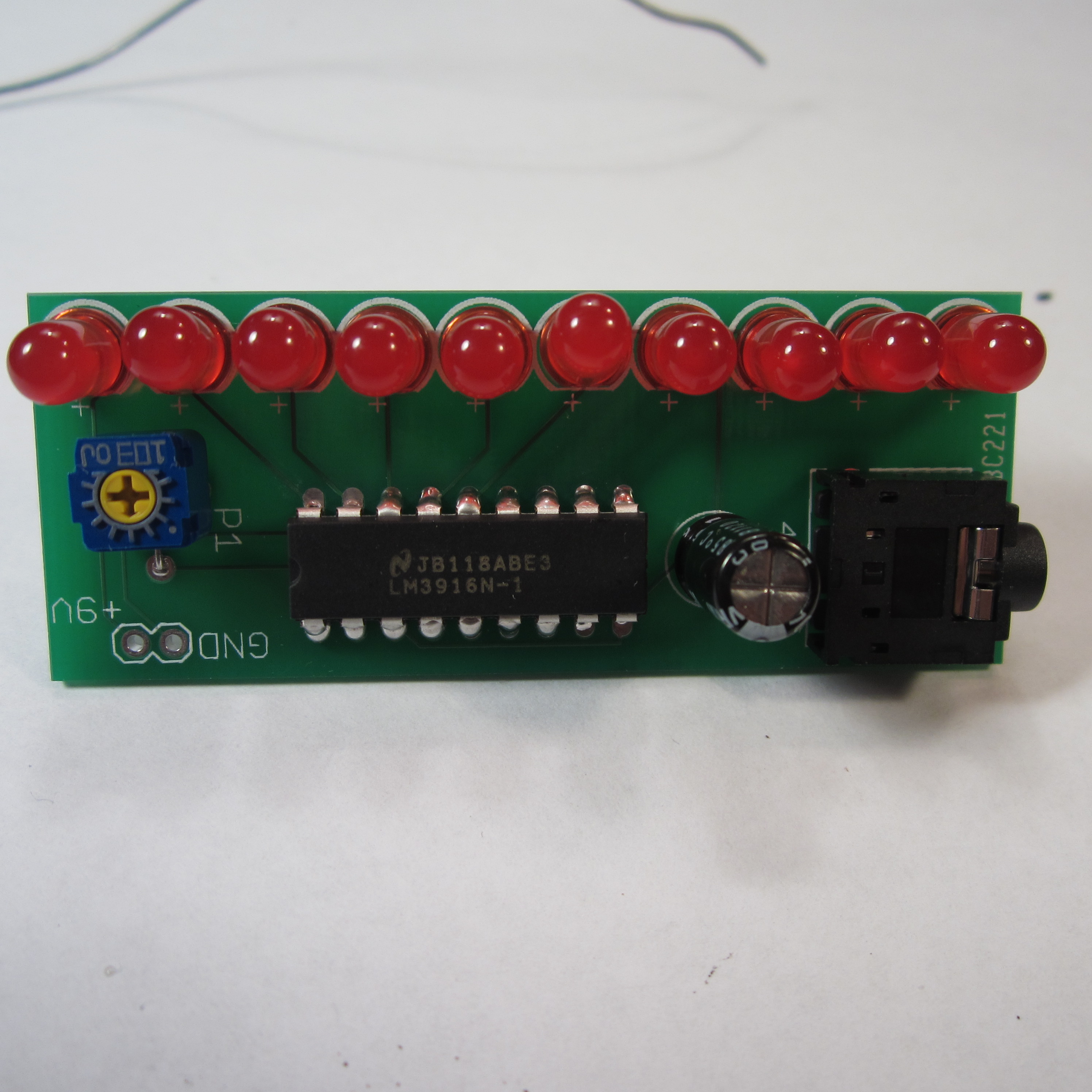
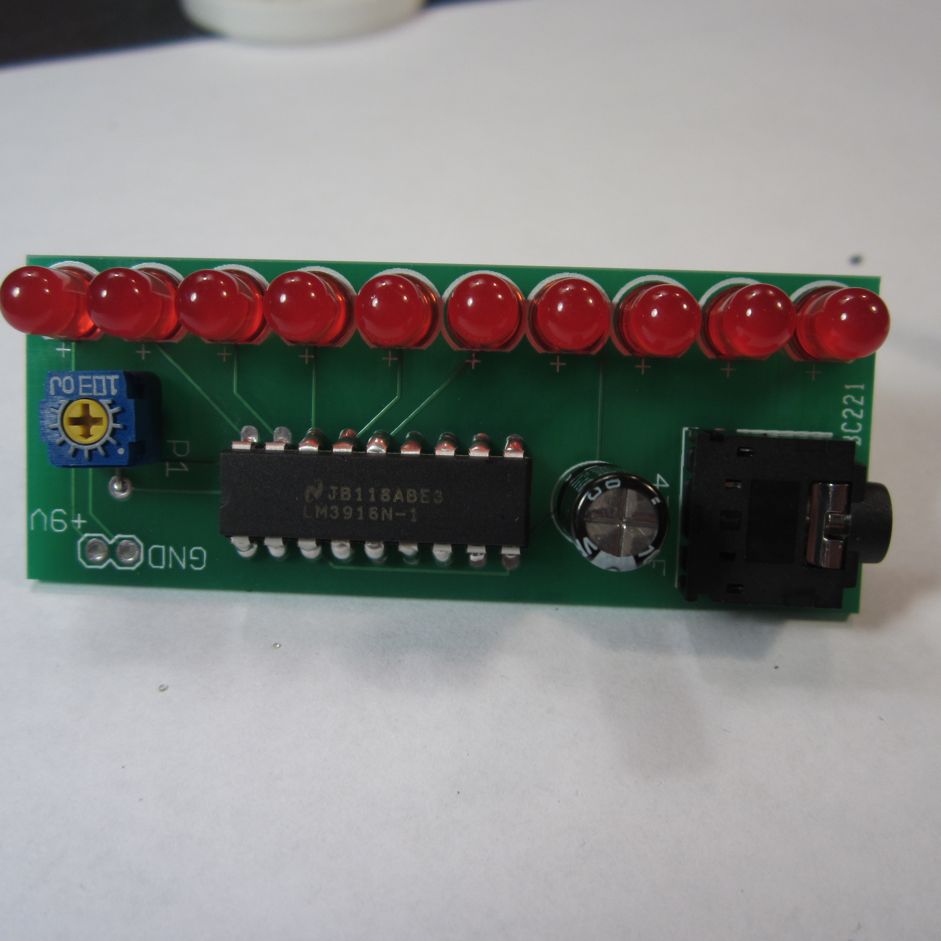
Mono VU Meter PCB
Files
- VU Meter V1.zip - VU Meter GERBER
- VU Meter.sch - VU Meter EAGLE Schematic
- VU Meter.brd - VU Meter EAGLE Board
Bill of Materials
| Qty | Part # | Description | Schematic ID | Source | |
|---|---|---|---|---|---|
| 1 |
|
SJ1-3524NG | CONN JACK STEREO R/A 4PIN 3.5MM | J1 | Source |
| 1 |
|
LM3916N-1 | LED BAR GRAPH DRIVER, 3916, DIP18 | IC1 | Source |
| 1 |
|
CT6EP103 | TRIMMER 10K OHM 0.5W TH | P1 | Source |
| 1 |
|
UVR1A471MED | CAPACITOR ALUM ELECT 470UF, 10V, RADIAL | C1 | Source |
| 1 |
|
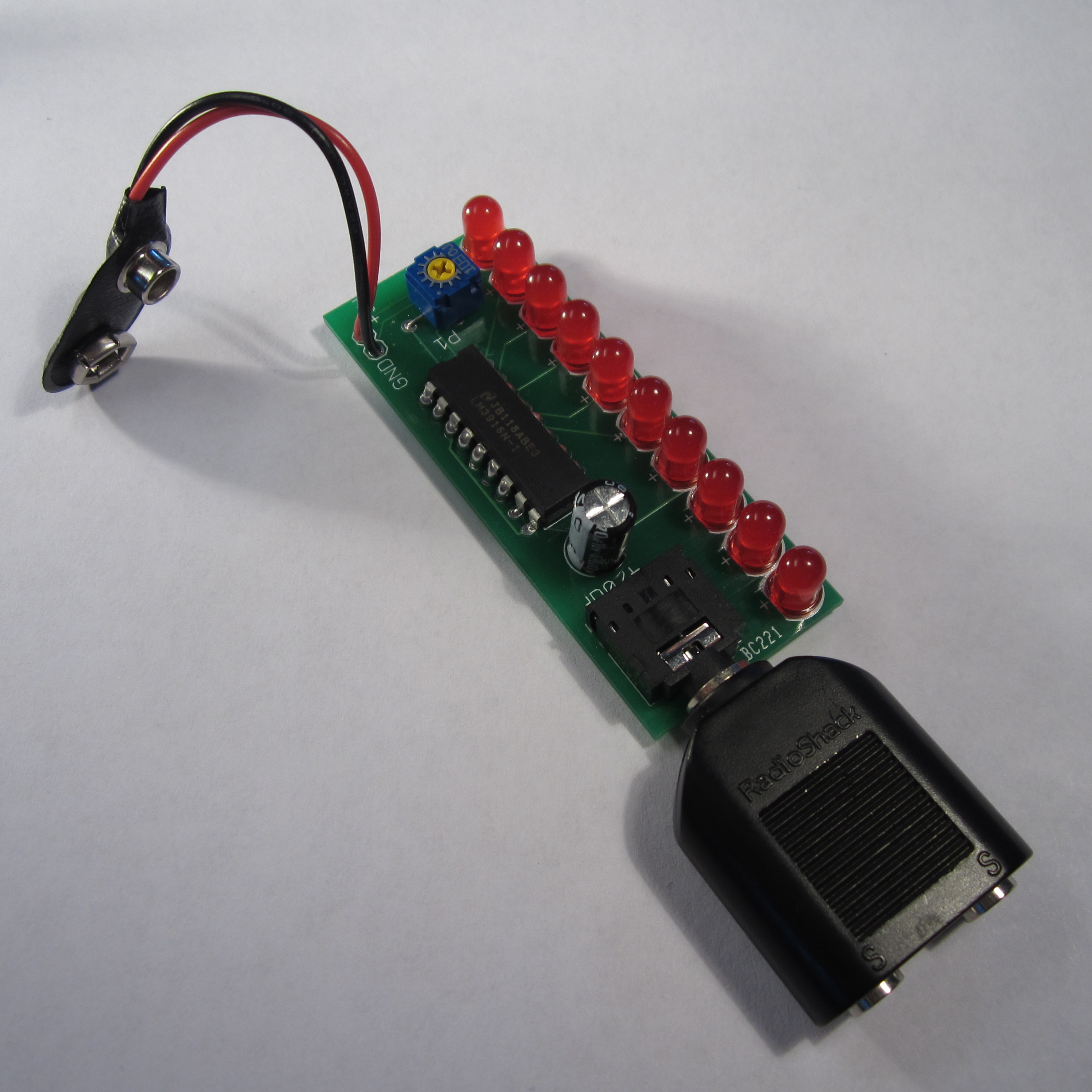
BS6I | SNAPS 9V 6" LEADS I-STYLE | JP1 | Source |
| 10 |
|
WP7113LID | 5MM LOW CURRENT RED LED, LAMP THOLE, BULK | LED1-10 | Source |
Download BOM w/o images
Download BOM w/ images
Steps
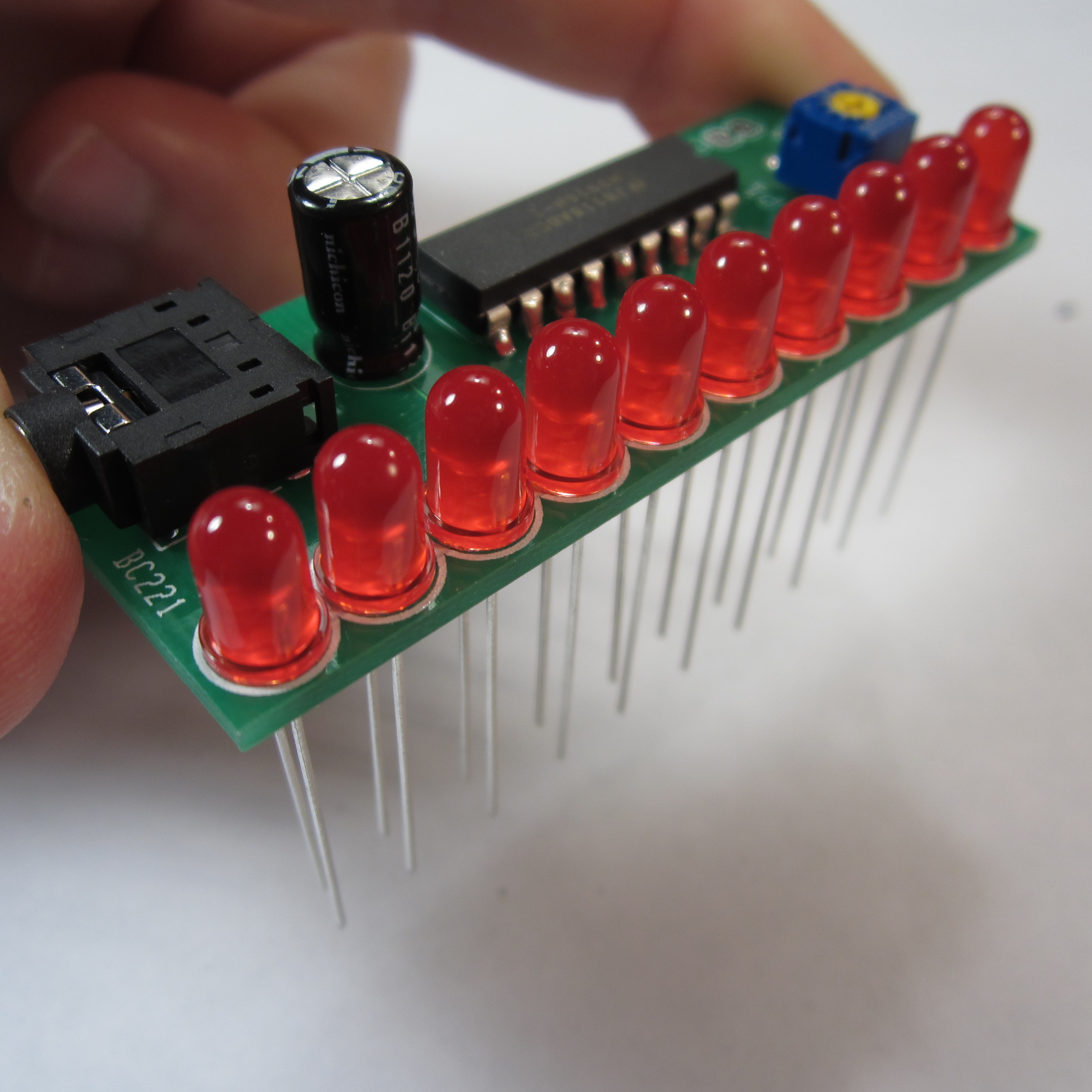
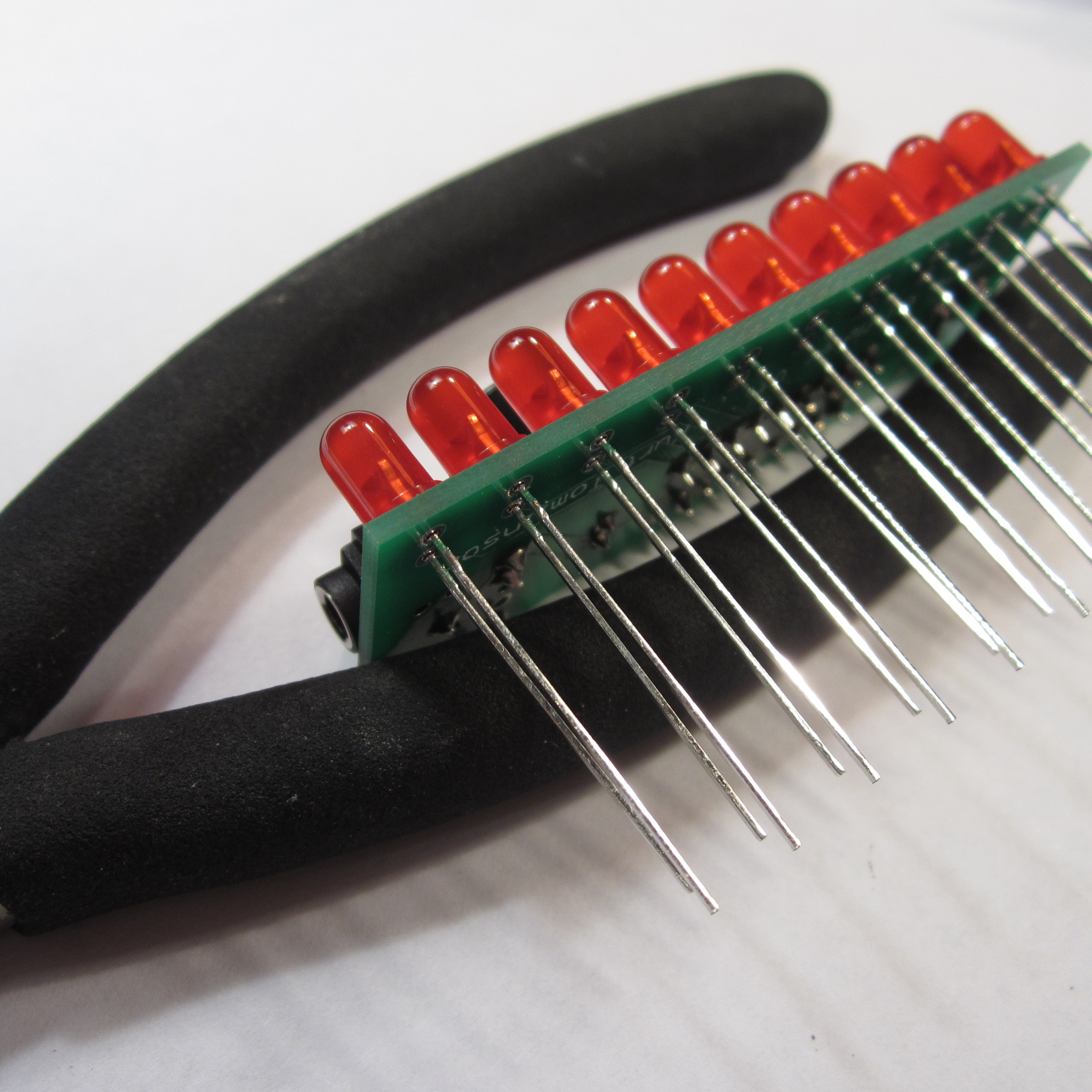
6. Solder LEDs
Insert all ten LEDs. Make sure the LEDs line up with the outlines on the PCB. The flattened side of the LED should be away from the board edge. Ignore the +'s on the PCB artwork. They are wrong.
Solder the outside leg of each LED. Then push the LEDs into place while remelting the solder on the outside leg. When you've got the LEDs positioned flush against the board, continue soldering the other leg of each LED.
In the photos you can see how the LED's aren't lined up very well at first. After I straightened them out by re-soldering the first leg, they look much better.
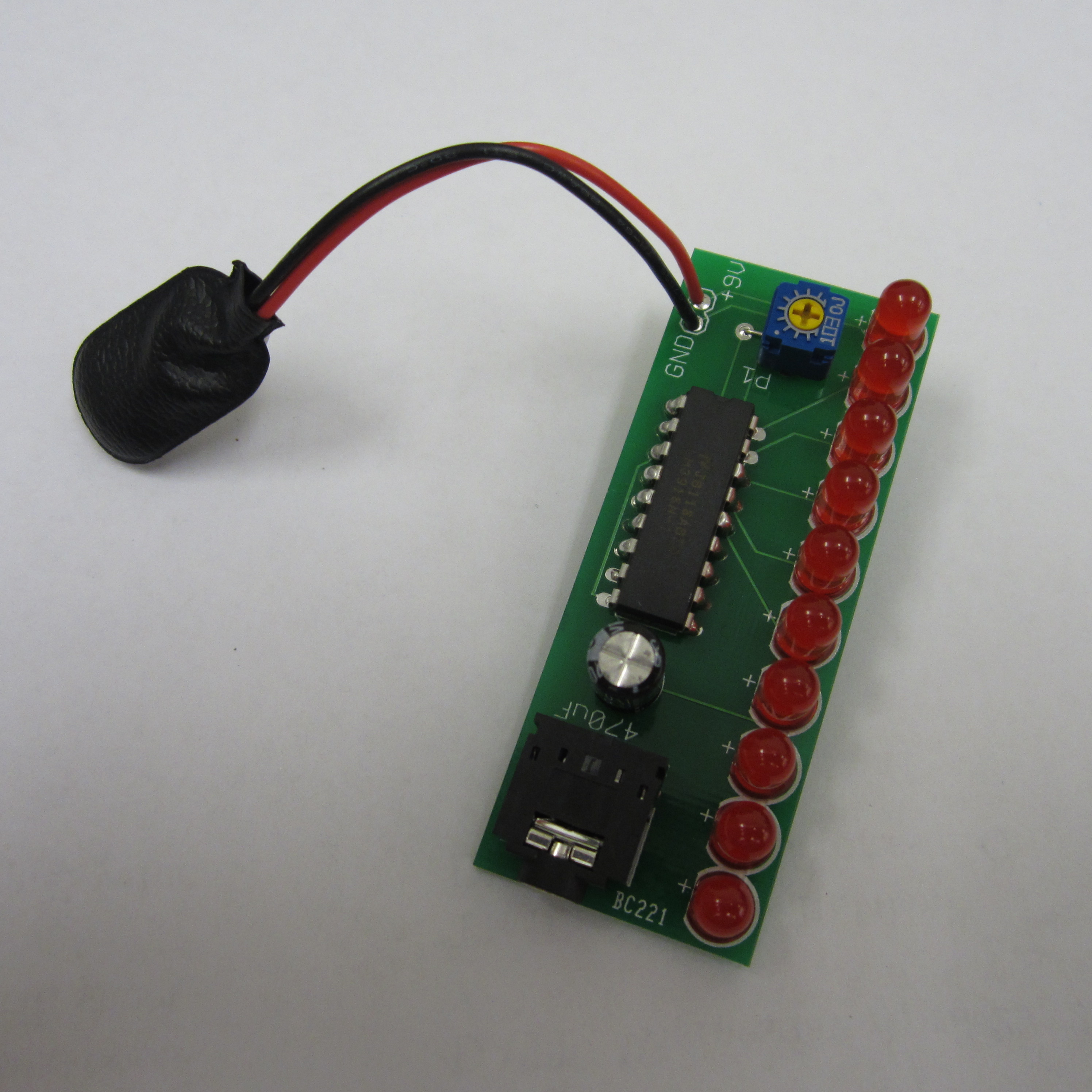
7. Solder 9V Battery Clip
Solder the 9V battery clip to the PCB. The black while goes in the hole marked ground. The red wire goes in the hole marked +9V.

8. Use It!
Plug a 9V battery into the 9V battery clip. Plug a stereo y-splitter into the audio jack on the VU Meter. Use a male-to-male 3.5mm audio cable to bring the audio signal from your audio source to the VU meter. Plug the 3.5mm cable from your speakers into the other hole on the y-splitter.
Use a small screw driver to adjust the potentiometer so that the loudest parts of music just barely light up the top LED. Enjoy the show!
Download steps w/o images
Download steps w/ images
Revisions
2 - added youtube link
1 - Initial project release
Add revision
blog comments powered by Disqus
Back


