-
Featured User: kurt

Open-source hardware project hosting is my passion. I spend most of my free time building neat gadgets or planning what I'll build next. I love building things, and I want to make Open Hardware Hub a place that inspires others to build, ...
-
Updates 2013 February 18
It's been a while, hasn't it? Well, that's ok because we've got a lot of updates to talk about. Most of these have been effective on the site fora couple weeks now. A few may or may not be active when this article gets posted, but they'll certainly be applied in the ...
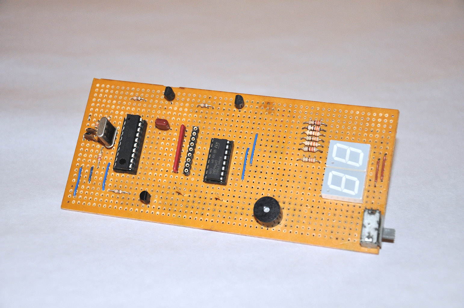
8bit bus monitor

Files
- portmon_schematic.zip - Schematic in SCH (EAGLE) and PDF formats
- portmon_source.zip - AT89S2051 source code and compiled HEX file
Bill of Materials
| Qty | Part # | Description | Schematic ID | Source | |
|---|---|---|---|---|---|
| 1 |
|
AT89S2051-24PU | IC, 8BIT MCU FLASH, 89S2051, DIP20 | IC1 | Source |
| 1 |
|
M74HC595B1R | 8 Bit Shift Register Output Latch (3-State) | IC2 | Source |
| 1 |
|
FOXLF036S | CRYSTAL, 3.579545MHz, 18PF, THRU HOLE | Q1 | Source |
| 3 | 2SC945 | 2SC945 | T1, T2, T3 | Source | |
| 2 |
|
HDSP-F101 | Low Current Seven Segment displays | SSD1, SSD2 | Source |
| 1 |
|
MCP320Q | Audible Signal | SG1 | Source |
| 1 |
|
CSC09A0110K0GPA | RESISTOR, BUS RES N/W, 8, 10KOHM, 2%, SIP | RN1 | Source |
| 3 |
|
PCF14JT22K0 | PCF Series Ø 2.3 x 6.5 mm 0.25 W 22 kOhm ±5 % Through Hole Carbon Film Resistor | R1, R2, R3 | Source |
| 3 |
|
PCF14JT10K0 | RES 10K OHM 1/4W 5% CARBON FILM | R11, R12, R13 | Source |
| 7 |
|
PCF14JT330R | RES 330 OHM 1/4W 5% CARBON FILM | R4, R5, R6, R7, R8, R9, R10 | Source |
| 2 |
|
K150J15C0GF5TL2 | Ceramic Multilayer Capacitor | C1, C2 | Source |
| 1 |
|
K104K15X7RF5TL2 | Ceramic Multilayer Capacitor | C3 | Source |
| 1 |
|
640456-2 | HEADER, VERTICAL, 0.1", 2WAY | TP1, TP2 | Source |
| 1 |
|
LPPB501NFFN-RC | 50 Position Total Single Row 1.27 mm Pitch Straight Female Header | SV1 | Source |
| 1 |
|
1101M2S3CQE2 | SLIDE SWITCH, SPDT, ON-ON | S1 | Source |
| 1 |
|
110-99-320-41-001000 | DIP Socket | IC1 | Source |
| 1 |
|
110-99-316-41-001000 | DIP Socket | IC2 | Source |
Download BOM w/o images
Download BOM w/ images
Steps
1. Assembling the circuit
- To assemble the circuit use the given schematic. It is highly recommended to use appropriate IC sockets for IC1 and IC2.
- For Q1 (Crystal) use any 3MHz crystal. We test this system with 3.575611MHz and 3.579545MHz crystals.
2. Attach seven segment display (SSD) to IC2
Connections between IC2 and SSD are as follows:
- IC Pin 1 - Segment G
- IC Pin 2 - Segment F
- IC Pin 3 - Segment E
- IC Pin 4 - Segment D
- IC Pin 5 - Segment C
- IC Pin 6 - Segment B
- IC Pin 7 - Segment A
3. Power Supply
This 8bit bus monitor requires 5V external power supply. In the idle mode this unit draws 15mA of current and in working mode (when inputs get change) this may raise up to 20mA – 30mA. Due to this low power profile, this system can also attach into the PSU of the "testing system".
Download steps w/o images
Download steps w/ images
Revisions
1 - Initial project release
Add revision
blog comments powered by Disqus
Back


