-
Featured User: kurt

Open-source hardware project hosting is my passion. I spend most of my free time building neat gadgets or planning what I'll build next. I love building things, and I want to make Open Hardware Hub a place that inspires others to build, ...
-
Updates 2013 February 18
It's been a while, hasn't it? Well, that's ok because we've got a lot of updates to talk about. Most of these have been effective on the site fora couple weeks now. A few may or may not be active when this article gets posted, but they'll certainly be applied in the ...
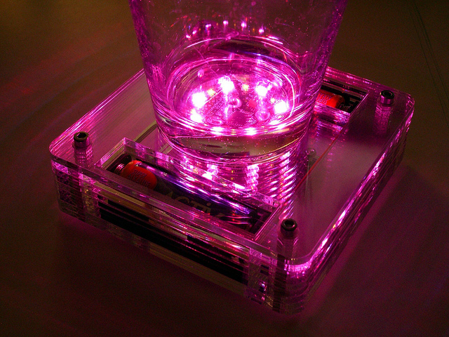
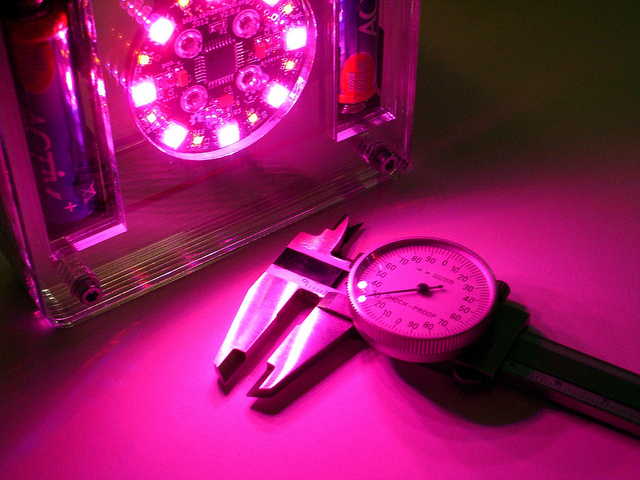
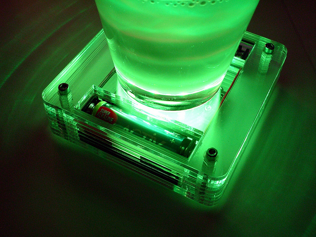
Mood light coaster
Files
- schematic.jpg - hand drawn :-)
- led_coaster_3mm_acrylic.svg - Ponoko cad data
Bill of Materials
| Qty | Part # | Description | Schematic ID | Source | |
|---|---|---|---|---|---|
| 1 |
|
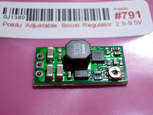
DC/DC Boost Regulator 2.5-9.5V | Source | ||
| 2 | Battery holder 1xAA | Make sure the battery holder's dimensions don't exceed the cutouts in the acrylic sheets. Holder with battery inserted should not be longer than 60mm, and not be higher / wider than 17mm. | Source | ||
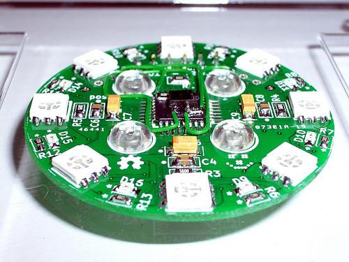
| 1 | RGB LED Ring V2 | Or build something of your own, which is more fun. | Source | ||
| 1 |
|
QRE1113GR | OPTO SWITCH, REFLECTIVE | Source | |
| 1 |
|
CRCW080591R0JNEA | THICK FILM CHIP RESISTOR | Source | |
| 1 |
|
CRCW080547K0FKEA | RESISTOR, 47KR, 125MW, 1% | Source |
Download BOM w/o images
Download BOM w/ images
Steps
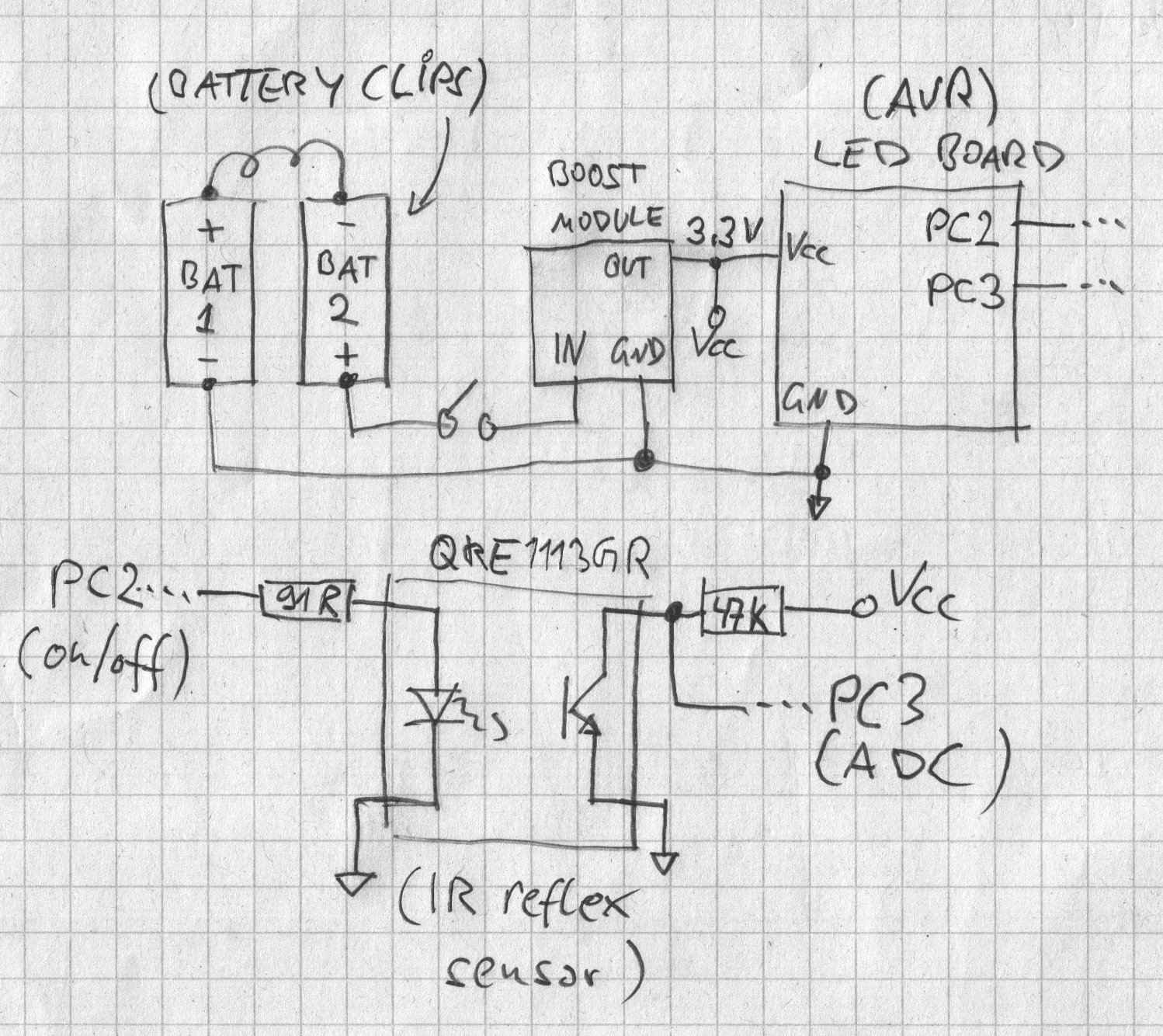
1. Test and adjust the DC/DC boost module
Temporarily connect the batteries to the booster circuit and adjust its output voltage to what the LED board requires. In this case it is 3.3V
2. Assemble the case and wire it up
That's the easy part. Simply stack all acrylic layers in the correct order, insert the hexagonal brass standoffs and tighten the bolts. Of course you will have made sure that the bolts and standoffs are of the correct length - either by buying the right kind in the first place or by cutting them to size (not recommended, as it's likely to add a few tics to your rage-meter).
Either make sure the switch and the battery holders fit the CAD file or adapt it to what you have access to.

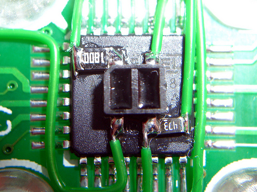
3. Add the IR reflex sensor
This is a bit of a dirty hack. I just used the sensor module from Pololu for parts. That was cheaper than ordering a single IR sensor somewhere else (shipping costs matter).
This requires to desolder the IR sensor and glue it to the center of the AVR. The remaining resistors (91R and 47k) were glued down as well, but the super glue didn't really want to stick. The electrical connections were made with 30-gauge wire (wire wrapping stuff). The teflon insulation is very heat resistant (which is good), but also almost impossible to remove - be patient and practise.
One I/O pin (PC2) drives the IR LED through the 91R resistor, the other pin (PC3) reads the analog signal at the open-collector of the photo transistor. The photo transistor + 47k pull-up resistor create a simple voltage-divider.
The detection range is pretty small, a couple of cm at most (about 1 inch max). The nice thing about using the ADC is that you can auto-calibrate at startup.
Detection of an object (e.g. a glass) works as the IR transmission of acrylic is well above 90% at the relevant wavelength.
4. Code
Well, this board is Arduino compatible, so please just write your own code. It is a piece of cake! There's no extra "AVR" voodoo required. And of course you can help yourselves with code published with the RGB LED RING V2 project.
Download steps w/o images
Download steps w/ images
Revisions
1 - Initial project release
Add revision
blog comments powered by Disqus
Back


