-
Featured User: kurt

Open-source hardware project hosting is my passion. I spend most of my free time building neat gadgets or planning what I'll build next. I love building things, and I want to make Open Hardware Hub a place that inspires others to build, ...
-
Updates 2013 February 18
It's been a while, hasn't it? Well, that's ok because we've got a lot of updates to talk about. Most of these have been effective on the site fora couple weeks now. A few may or may not be active when this article gets posted, but they'll certainly be applied in the ...
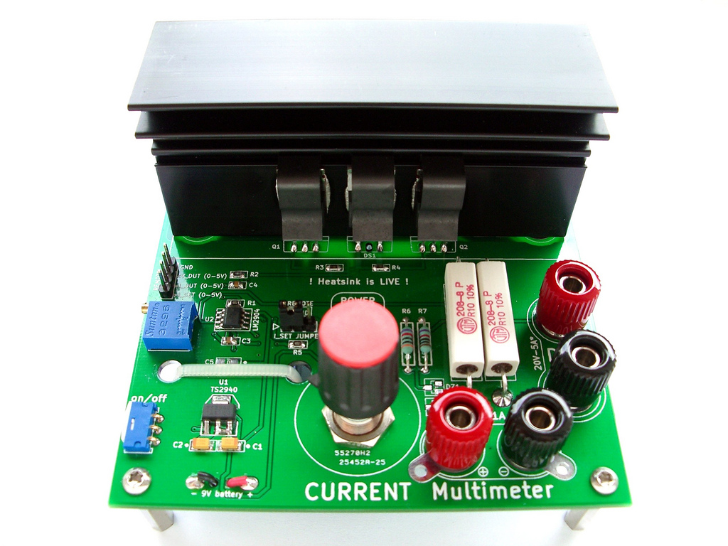
Simple DC Dummy Load

Files
- YauDL-V1.00.zip - V1.00 design files (KiCad + gerbers)
- YauDL-V1.00__schematic.pdf - V1.00 schematic
Bill of Materials
| Qty | Part # | Description | Schematic ID | Source | |
|---|---|---|---|---|---|
| 2 |
|
IRL3803PBF | 30V Single N-Channel HEXFET Power MOSFET in a TO-220AB package | Q1, Q2 | Source |
| 1 |
|
LM2904DG | OP AMP, DUAL IND SPEC, 2904, SOIC8 | U2 | Source |
| 1 |
|
TS2940CW50 RP | U1 | ||
| 1 |
|
534B1203JCB8872 | POTENTIOMETER, 2W 20K | RV2 | Source |
| 1 | 64P104T000 | MULTITURN CERMET TRIMMER | RV1 | Source | |
| 2 |
|
AC05000001007JAC00 | RESISTOR, 5W, 5%, 0R1 | RP1, RP2 | Source |
| 1 |
|
597-5311-407F | LED, 0805, GREEN | D1 | Source |
| 1 |
|
HH-3449 | BATTERY RETAINER CLIP | BT1 | Source |
| 1 |
|
MBR1045G | DIODE, SCHOTTKY, 10A, 45V | DS1 | Source |
| 2 |
|
08055C104KAT2A | CAPACITOR, 0805, 0.1UF, 50V | C3, C4 | Source |
| 2 |
|
1206YD106KAT2A | CAPACITOR, 1206, 10UF, 16V, X5R | C6, C7 | Source |
| 2 |
|
TAJA106K016RNJ | CAPACITOR, CASE A, 10UF, 16V | C1, C2 | Source |
| 2 |
|
BZX84C5V6 | DIODE, ZENER, VZ 5.6V | DZ1, DZ2 | Source |
| 1 |
|
CRCW06030000Z0EA | RESISTOR, 0603, 0R,0.1W,±1% | RGND1 | Source |
| 2 |
|
CRCW0805100RFKEA | RESISTOR, 0805, 100R , 1%,0.125W | R3, R4 | Source |
| 1 |
|
CRCW0805100KFKEA | RESISTOR, 0805, 100KR, 1%,0.125W | R2 | Source |
| 2 |
|
CRCW080510K0FKEA | RESISTOR, 0805, 10KR , 1%,0.125W | R1, R5 | Source |
| 1 | Alutronic PR127/94/M3 | Heatsink for multiple TO-220 packages + 3pcs mounting clips | HS1 | Source | |
| 1 | Resistor, 30k, 0.6W, 0.1% | R6 | |||
| 1 | Resistor, 10k, 0.6W, 0.1% | R7 | |||
| 2 |
|
111-0703-001 | BINDING POST, 15A, #6-32, STUD, BLACK | Source | |
| 2 |
|
7006 | BINDING POST, 15A, #6-32, STUD, RED | Source |
Download BOM w/o images
Download BOM w/ images
Steps
1. Theory of operation
This is very simple, a basic opamp application. In essence it is just a voltage follower or buffer.
The reference voltage is created by the trimmer potentiometer, which draws its power from a 5V regulator. Instead of using the output of the opamp as the feedback, the voltage drop across the shunt resistors is used. The opamp drives the MOSFETs. As the shunt resistor is small a 2nd opamp is inserted into the control loop to pre-amplify that voltage. Otherwise the output voltage of the trimmer-pot would have to be rediculously small.
To prevent unwanted oscillations the output of the opamps is fed back into the inverting inputs using a small ceramic capacitor on both opamp stages. This clamps the AC gain to 1. Inevitable losses in the system reduce any unwanted AC signal to naught.
The MOSFET driving opamp adjusts its output in such a way that the current through the shunt resistors matches the set current.
2. Assembly
Apply flux, populate the part, clean the tip, solder - Reapet until done.
Start with the on/off switch and work youself up to the voltage regulator and tantalum capacitors - via the battery clip and power indicator LED + resistor. Hook up a battery, turn it on and measure the regulator's output voltage. It should be pretty close to 5.00V - nothing should get hot or even slightly warm. As you may already have expected, the LED will light up when the device is powered.
With a stable 5V present on the board, continue with the opamp and any remaining small parts. Don't forget to populate RGND1 and C6,C7 on the back side.
Make sure the 10-turn potentiometer is wired up correctly! The resistance between the wiper (middle pad on the pcb) and GND (left pad) should be minimal when it is turned all the way to the left.
When mounting the semi-isolated binding posts (M4 mounting hole - the closest non mitricized equivalent would be ones with "6-32" studs) put some solder onto the top pad, so the little teeth on the post's base can dig into it. But not too much either - you want these things to be perferctly vertical and not some kind of 'Leaning Tower of Pisa'.
Now insert the TO-220 packages in the right places and tentatively mount the heatsink. Adjust its position so the MOSFETs and the Schottky diode fully touch the surface. Attach all clips and slightly tighten the heatsink's mounting screws. Soldering time again.
Remove the heatsink again. You can just pull it off, then slide out the clips. Apply a small amount of thermal compound (the same stuff you'd use for a CPU in a PC) and spread is evenly on the TO-220 parts. Excess good will be squeezed out later, so don't use too much. Remount the heatsink, make it touch the TO-220 packages and tighten down the screws. Attach the mounting clips again and remove any excess goop.
Inspect the board and look for shorts. Cleaning would be a good idea as well. 100% isopropyl alcohol works nicely for removing flux residue.
3. Calibration
Turn the potentiometer all the way to the left and turn on the device. A voltmeter connected to the 'Multimeter' binding posts should read 0, definitely NOT more than 5mV. Measure the voltage between the wiper and GND and turn the knob clockwise until you get to 1.00V - now don't touch the knob anymore. Turn the dummy load off.
Connect a power supply in series with an A-meter to the 'DUT' binding posts. If you have one with current control, set the maximum to 1.2A for now and set the voltage to 5V. Make sure polarity is correct. As long as the dummy load is off the should be absolutely no current flowing through it. Turn on the power supply and the dummy load and measure the actual current going through it. It will most likely be off quite a bit. Take a small screwdriver and adjust the I_CAL trimmer potentiometer until you see 1.00A - the voltage at the 'Multimeter' binding posts should now read 1.00V. If you're not quite there yet do some more iterations. The goal is to reproduce the voltage set on the potentiometer on the 'Multimeter' binding posts as accurately as possible.
The heatsink will get warm or even slightly hot, this is normal.
If you've come thus far it is not time to 'play' with the knob a bit and see if the dummy load behaves nicely. 2 full turns should equal 1A of current, 4 full turns 2A and so on. It should be perfectly linear.
Finally test the reverse polarity protection. Simply reverse the DUT connections. No current should flow.
4. Normal operation
Always make sure the dummy load is OFF and the potentiometer is wound all the way to the left before you connect it. Always start at 0 current and wind up the wick.
With the right heatsink this device will happily take 20W continuously, but the heatsink will get hot. Did I mention the heatsink will get HOT? You should make sure it does not exceed the boiling point of water (wet finger test). If the heatsink is still quite cool you may dump a lot more than 20W into it.
5. Remote operation
Turn everything off.
Prepare your remote control jig (PC, microcontroller...) to output a TRUE analog signal in the 0-5V range. If you feed a PWM signal into the dummy load, the average current may be alright, but there will be significant current overshoot. That may or may not ruin your day. Just use a simple RC lowpass filter with a low-enough cut-off frequency and you should be good to go. If you have a scope, check the output of the filter and check the current output on the dummy load.
Connect the analog signal to the I_SET pin and GND to GND. You can also get the DUT current and voltage on two other pins (both scaled to 0-5V with the precision voltage divider R6,R7 and clamped with Zener diodes). Then flip the jumper to 'remote' and start to use it. DO NOT let the I_SET pin float!
This setup can be used to measure battery capacity and extract the discharge curve, U(I) characteristics and a whole lot of other things.
Download steps w/o images
Download steps w/ images
Revisions
1 - Initial project release
Add revision
blog comments powered by Disqus
Back


