-
Featured User: kurt

Open-source hardware project hosting is my passion. I spend most of my free time building neat gadgets or planning what I'll build next. I love building things, and I want to make Open Hardware Hub a place that inspires others to build, ...
-
Updates 2013 February 18
It's been a while, hasn't it? Well, that's ok because we've got a lot of updates to talk about. Most of these have been effective on the site fora couple weeks now. A few may or may not be active when this article gets posted, but they'll certainly be applied in the ...
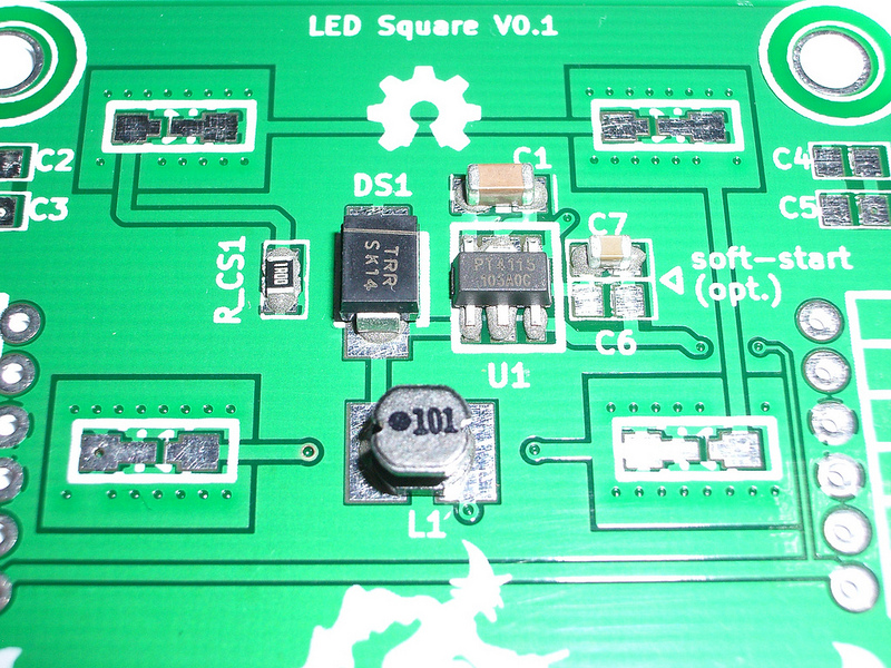
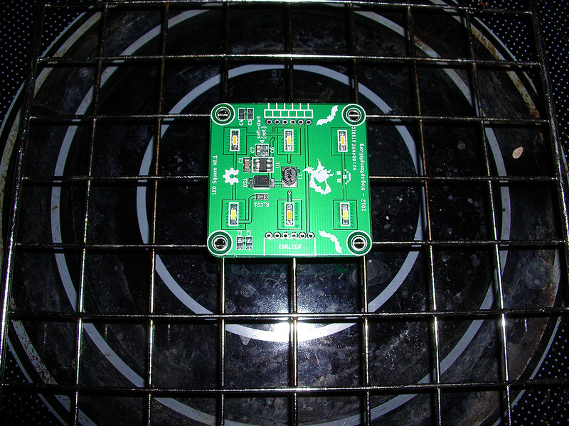
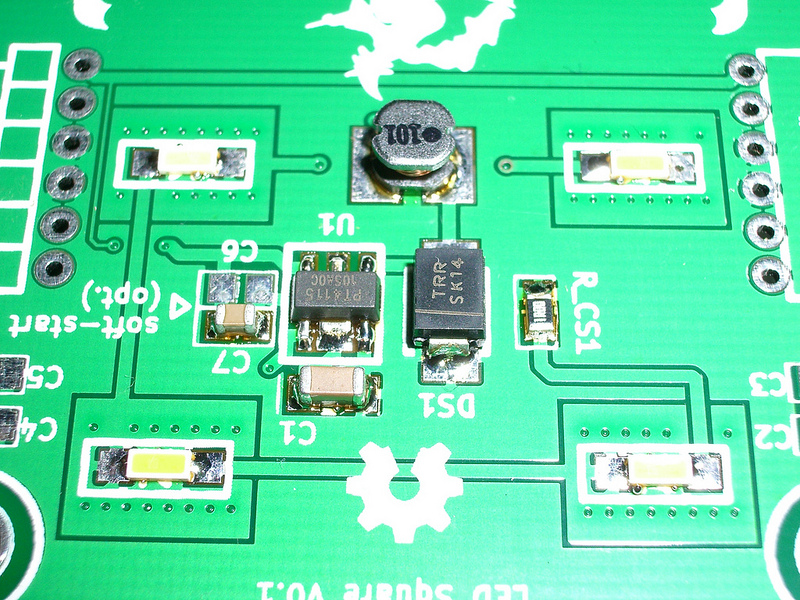
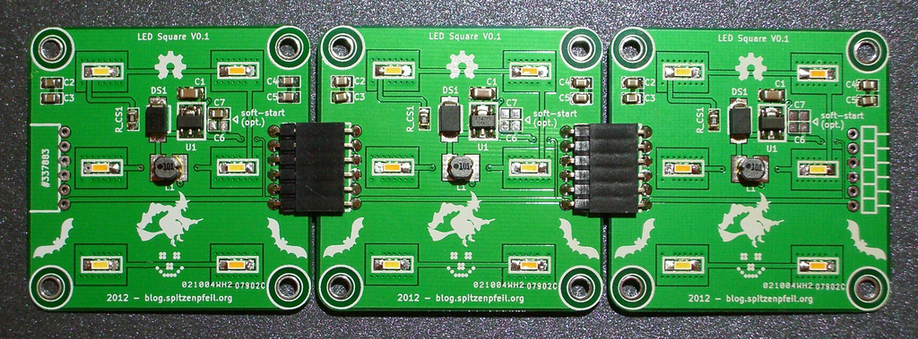
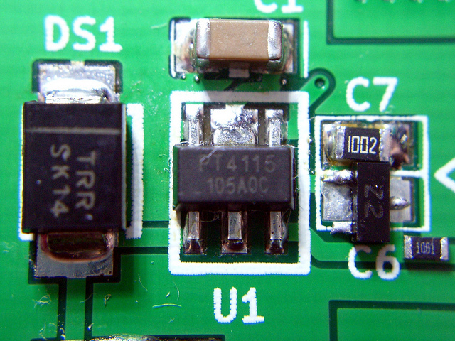
LED Square - PT4115


Files
- LED-Square_PT4115.zip - Design files for the version shown here
Bill of Materials
| Qty | Part # | Description | Schematic ID | Source | |
|---|---|---|---|---|---|
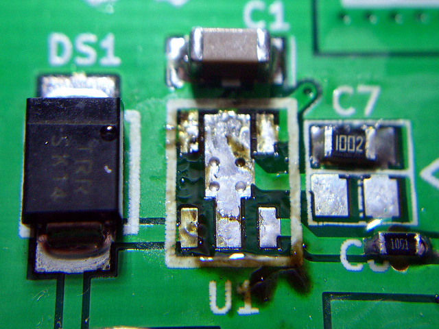
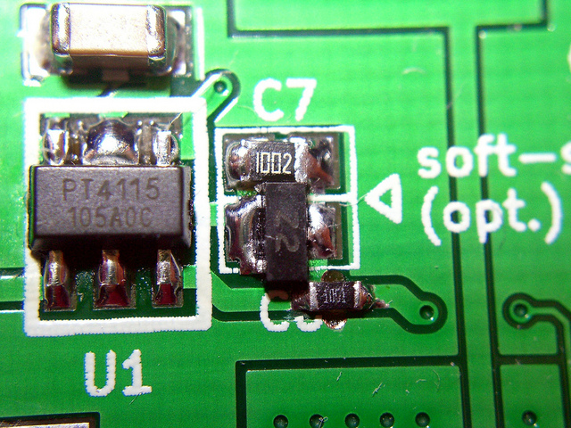
| 1 | PT4115 | Powertec PT4115, buck LED driver, 30V, 1.2A | U1 | Source | |
| 1 |
|
LQH43CN680K03L | INDUCTOR, 1812 CASE, 68µH, 10% | L1 | Source |
| 1 |
|
MBRS140T3G | DIODE, SCHOTTKY, 1A, 40V | DS1 | Source |
| 1 | GRM31CR61H106KA12L | CAPACITOR, 1206, 10UF, 50V | C1 | Source | |
| 4 |
|
CC1206KKX5R7BB106 | CAPACITOR CERAMIC, 10µF, 50V, X7R, 0805 | C2-C5 | Source |
| 1 |
|
ERJ-6RQF1R0V | RESISTOR, 0805, 0.125W, 1%, 1R | R_CS1 | Source |
| 6 |
|
Nichia NSSW157A | Tiny high-efficiency LEDs | Source | |
| 1 |
|
CRCW080510K0FKEA | RESISTOR, 0805, 10KR , 1%,0.125W | C6 | Source |
Download BOM w/o images
Download BOM w/ images
Steps
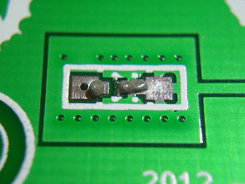
1. Assembly / reflow
Get a good brand solder paste that comes in a syringe. Make sure you also get the plunger and a small nozzle. Adding too much paste is very easy. Personally I use 'EDSYN CR44' (leaded) and I'm happy with it. Solder paste should be stored in a fridge to prevent it from going bad. I found that fizzy vitamin supplement pills come in tubes that are ideal for storing small syringes. They are air-tight.
Add small dabs of paste onto the circuit board. The amount shown in the pictures is a bit too much, use less. Place the parts using curved tweezers. Try to get good alignment, but don't get too obsessed with it.
Use a heat source (hot-plate, toaster, hot-air tool...) to melt the solder. It will take some time, but you will clearly see when it happens. There may be a bit of smoke, ensure good ventilation. Make sure all parts have been 'cooked' adequately. With leaded solder paste the joints should be shiny.
Usually the alignment of parts improves when the solder melts. If some parts should not snap into position, give them a nudge with the tweezers. Parts that go 'tombstone' will need to be fixed later with an iron. Either pull them off now or do it later.
You will find plenty of videos on youtube to familiarize yourself with the SMD reflow process. Quality varies, so watch a couple of them.
Add the through-hole parts after completing this step.
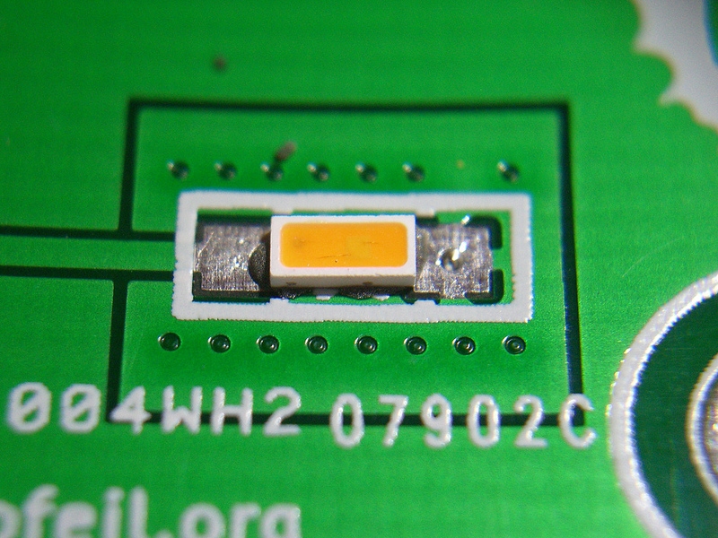
2. Test, clean, interlink and place where needed
Look for solder bridges and stray solder blobs (little spheres of shiny solder paste) and take care of them.
Test the LEDs with a diode tester.
If everything works, clean the boards with isopropyl alcohol.
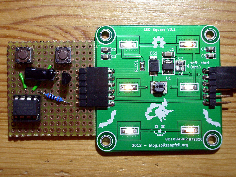
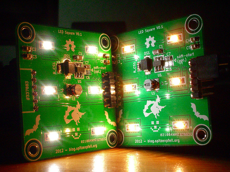
Now connect 18-24V DC and a 5V PWM signal to control the LED board(s). This is easily created with say an ATtiny13 with two up/down buttons, or just use a 555 timer-chip. PWM frequency should be above audible range.
Make sure not feed more than 5V into the DIM pin. If you handle the boards while powered, keep in mind that skin resistance may be low enough to allow a destructive voltage to reach the DIM pin when you accidently touch the positive supply line. This problem is solved in later revisions using a Zender diode.
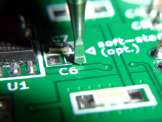
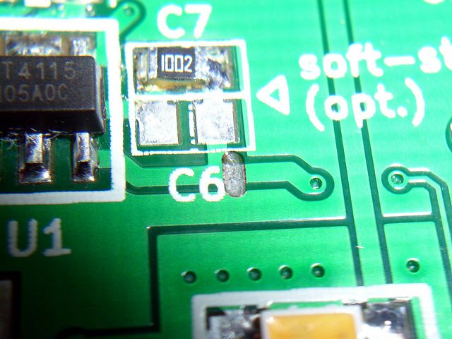
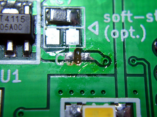
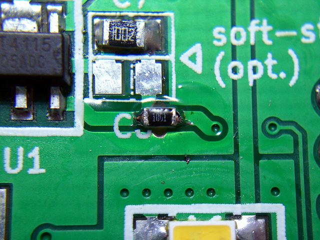
3. ESD-protection upgrade for DIM input
As there were far too many losses during the time I played with these boards, I just had to 'back-port' the fixes of the next version. The alternative would have been more chips going into the trash.
This step shows how I added a 1k dropper resistor and a 5.1V Zener diode.
When driving multiple boards, care must be taken that more than 2.5V (e.g. 3V) reach the DIM pin on the chip. If the PWM peak voltage is below 2.5V, LED brightness also scales with that voltage and not just with duty-cylce.
Download steps w/o images
Download steps w/ images
Revisions
2 -
1 - Initial project release
Add revision
blog comments powered by Disqus
Back


