-
Featured User: kurt

Open-source hardware project hosting is my passion. I spend most of my free time building neat gadgets or planning what I'll build next. I love building things, and I want to make Open Hardware Hub a place that inspires others to build, ...
-
Updates 2013 February 18
It's been a while, hasn't it? Well, that's ok because we've got a lot of updates to talk about. Most of these have been effective on the site fora couple weeks now. A few may or may not be active when this article gets posted, but they'll certainly be applied in the ...
IR switch with PWM

Files
- LED-strip_PWM_IR.zip - Firmware (source + compiled)
Bill of Materials
| Qty | Part # | Description | Schematic ID | Source | |
|---|---|---|---|---|---|
| 1 |
|
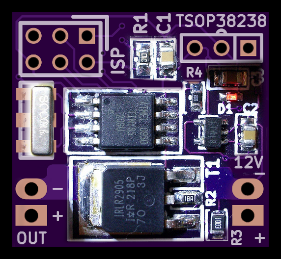
ATTINY85V-10SU | AVR MCU, 8K FLASH, 512B RAM, SOIC8 | IC1 | Source |
| 1 |
|
MCP1804T-5002I/OT | IC, LDO, 5V, 150MA, 5SOT23 | U2 | Source |
| 1 |
|
TSOP38238 | IR RECEIVER, 45M, THROUGH HOLE | U1 | Source |
| 1 |
|
IRLR2905PBF | 55V Single N-Channel HEXFET Power MOSFET in a D-Pak package | T1 | Source |
| 1 |
|
CRCW060310K0JNEA | RESISTOR, 10KR, 0.1W, 5% | R1 | Source |
| 1 |
|
ERJ-3EKF1001V | RESISTOR, 0603, 0.1W, 1%, 1K | R4 | Source |
| 1 |
|
CRCW0603150RFKEA | RESISTOR, 0603, 150R , 1%, 100MW | R2 | Source |
| 1 |
|
CRCW060320K0FKEA | RESISTOR, 0603, 20KR , 1% | R3 | Source |
| 2 |
|
08055C104KAT2A | CAPACITOR, 0805, 0.1UF, 50V | C1, C2 | Source |
| 1 |
|
GRM21BR71C475KA73L | CAPACITOR, 0805, X7R, 16V, 4.7UF | C3 | Source |
| 1 |
|
HSMG-C190 | Surface Mount ChipLEDs | D1 | Source |
| 1 |
|
CSTCC8M00G53-R0 | RESONATOR, SMD, 8.0MHZ | Q1 | Source |
Download BOM w/o images
Download BOM w/ images
Steps
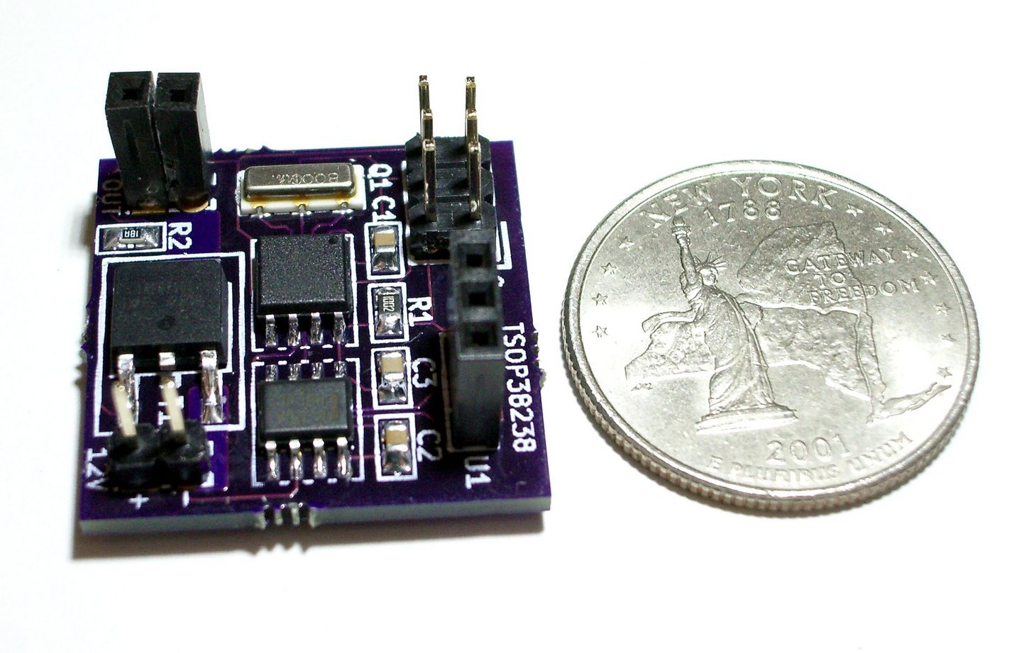
1. Specifications
- Dimensions: 25x23mm (a bit smaller than 1in squared)
- Made for 12V DC
- Low standby power
- Switch current: 5A, more with heatsink
- For resistive loads (LEDs) only
- PWM capable for brightness control
- 38kHz IR receiver
- Can be 'taught' any IR code - requires firmware recompilation
- Firmware includes a 'scan' mode to capture any IR code and send data to a computer
You can find it on tindie.com
The IR-codes used in the demo-code were derived from a small and cheap IR remote (NEC protocol) that is currently available at Adafruit.
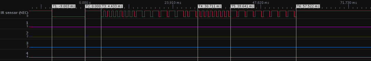
2. Capturing IR codes
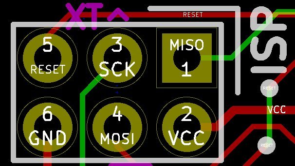
I'll asume you have an ISP programmer available and know how to use it. This could be one of these: avrispmkII (and clones), usbtiny, usbasp, ArduinoISP... You'll also need a USB to serial converter (FTDI cable or equivalent). The firmware of the board includes a scan-mode, which measures incoming IR data and outputs the pulse-durations using the soft-UART (9600,8,N,1). I'll only cover the process for one kind of IR remote control. Making it work with multiple different protocols and packet lengths only requires a bit of coding. You can do it yourself if need be.
# Switch the board into capture mode:
- Connect the IR Sensor.
- Connect 'SCK' to the RX-pin of the serial adapter.
- Make sure to be far away from disturbing light sources (fluoros...)
- Connect '+' and '-' on the 12V-side of the board to the corresponding pins of the USB adapter board (5V and GND). The status LED should come on and stay lit.
- Within 5 seconds start sending IR codes, the board will go into scan mode and send data via the serial port.
If you get a lot of trailing '0'-s at the end of each IR packet, reduce the NUMPULSES #define in 'IR_codes.h' to chop them off.
3. Adding new codes to the firmware
The output of the captured data looks like this:
#define ir_code_1 {\
801,\
214,\
50,\
[...some more data...]
0}\
1) Transfer to 'IR_codes.h' and set a unique name instead of 'ir_code_1', e.g. new_code.
2) Add that unique name to
#define NUMBER_OF_IR_CODES 5 // does not include the repeat-code, which I don't consider as a "full" code.
const uint16_t PROGMEM IRsignals[NUMBER_OF_IR_CODES][NUMPULSES] = {
vol_up,
vol_down,
arrow_up,
arrow_down,
new_code};
3) Update 'IR_receiver.hpp'
// all elements EXCEPT (REPEAT_CODE, MISMATCH and NOT_SURE_YET) must be in the same
// order (if present at all) as in the PROGMEM array IRsignals! These 3 special elements
// must ALWAYS be there.
typedef enum {
VOL_UP,
VOL_DOWN,
ARROW_UP,
ARROW_DOWN,
NEW_CODE,
// DO NOT EDIT THESE LAST 3!
REPEAT_CODE = 66,
MISMATCH = 77, // only returned if something goes terribly wrong
NOT_SURE_YET = 99 // this should NEVER be returned as a result
} IR_code_t;
4) Recompile the firmware. I use Code::Blocks, but there's also a simple 'compile.sh' script.
5) Reprogram the ATtiny85.
4. Test, test, 1..2..3
Check for new IR data with 'IR_available()', retrieve the received IR code with 'eval_IR_code()'. Once you have the identifier of that code in a varialbe, just use a switch-statement to process. The demo-code does just that. That way you can easily identify and use IR-remote buttons by name and write human-readable code.
To have a look behind the scenes, uncomment '//#define DEBUG' in 'IR_receiver.hpp' and the board will print measured vs. stored data until it finds a match.
If you get too many false readings, try playing with the FUZZINESS number. Higher values allow for more deviation from the stored reference.
Use the onboard LED (connected to SCK) as an indicator that IR data is being received or recognized. It will also blink when sending out serial data.
5. Application ideas
12V LED strip controller, remote switch for Halloween props (yes, a bit late...)
Download steps w/o images
Download steps w/ images
Revisions
3 -
2 -
1 - Initial project release
Add revision
blog comments powered by Disqus
Back


