-
Featured User: kurt

Open-source hardware project hosting is my passion. I spend most of my free time building neat gadgets or planning what I'll build next. I love building things, and I want to make Open Hardware Hub a place that inspires others to build, ...
-
Updates 2013 February 18
It's been a while, hasn't it? Well, that's ok because we've got a lot of updates to talk about. Most of these have been effective on the site fora couple weeks now. A few may or may not be active when this article gets posted, but they'll certainly be applied in the ...
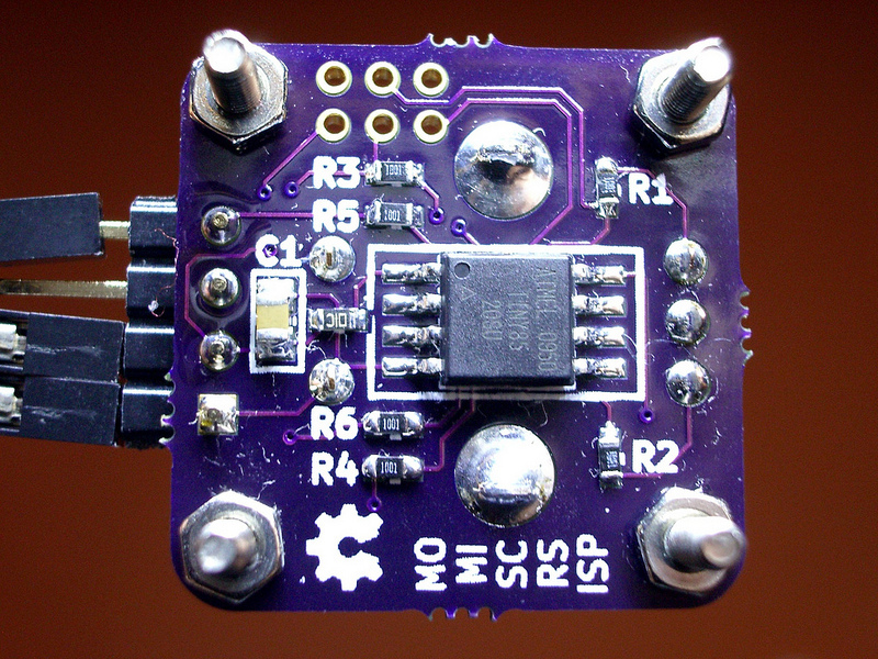
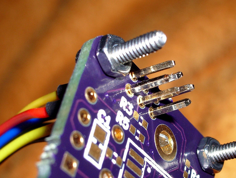
The Knob


Files
- Serial-Knob.zip - Demo firmware
Bill of Materials
| Qty | Part # | Description | Schematic ID | Source | |
|---|---|---|---|---|---|
| 1 |
|
ATTINY25-20SU | AVR MCU, 2K FLASH, 128B RAM, SOIC8 | IC1 | Source |
| 1 |
|
EN12-HS22AF30 | Mechanical Encoder Rotary Incremental Flat 1.4oz.in Straight Gray Digital Square Wave 24PPR Through Hole PC Pins | ENC1 | Source |
| 1 |
|
0805ZG475ZAT2A | CAPACITOR, 4.7 UF, 10V, 0805, Y5V | C1 | Source |
| 1 |
|
SML-310YTT86 | SML-310 Series Yellow 0603 6.3 mcd Clear 2.1 V LED Surface Mount | D1 | Source |
| 1 |
|
ERJ-3EKF1002V | RESISTOR, 0603, 0.1W, 1%, 10K | R7 | Source |
| 6 |
|
ERJ-3EKF1001V | RESISTOR, 0603, 0.1W, 1%, 1K | R1-R6 | Source |
Download BOM w/o images
Download BOM w/ images
Steps
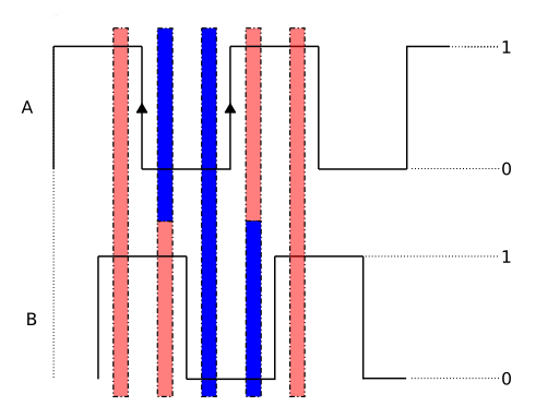
1. Reading the encoder
A quadrature encoder has exactly four states, which are determined by the 2 output signals A and B. These states may be called: (00,01,10,11). The signals A and B are 90° out of phase, shifted with respect to each other. Ideally only one signal can change at any given time, never both. That way one can determine which one changes first (A before B, B before A), which carries the information about direction of rotation.
You can use an edge-triggered interrupt to do it, but that requires absolutely clean edges. No switch bouncing tolerated. Otherwise the cpu load would surge. We don't want that. This is also not about reading a high-frequency signal, so the polling approach is sufficient. We also don't care about sleep modes, so there's no need for interrupts to wake up the micro.
As it happens, there is already a timer interrupt running at 1kHz, which provides 'time' and 'delay' functionality (recycled code from another project). Reading and evaluating the encoder state is simple enough, so we just plug that into the system-ticker routine.
By comparing the current vs. the previous encoder state, one can determine if a step has been made and in which direction. This assumes that every step is recognized. If steps are skipped, there are disambiguities and it can't be determined for sure what has happened. Time to increase the polling frequency. But for a hand-turned knob with just 24 ticks per revolution this extremely unlikely.
A typical time-sequence of states may look like this:
... - 11 - 01 - [ 00 - 10 - 11 - 01 ] - 00 - 10 - ...
Going from left to right could be clockwise rotation, right to left anti-clockwise rotation.
The state names (00,01...) also match the bits that are set or unset in the GPIO input register of the microcontroller. One way to make the decision of what step has taken place is to use a lot of if-statements, but that is a lot of text to write. A simpler way is to create a truth-table of sorts (array), with elements of {+1, 0, -1}, representing the step-direction. The bit-values of the encoder states (previous and current) are joined into one byte, which will become the index of the array. If a combination indicates a valid step forwards, the associated array-element will be '+1'. A negative step will of course be represented by '-1'. No change or any invalid combination (e.g. from 00 to 11) will get a '0'.
---
The main loop checks for a changed encoder state (flag is set by the interrupt), and processes the data - i.e. send out a status-byte via serial. Done.
Download steps w/o images
Download steps w/ images
Revisions
7 - Added a video.
6 - Changed the title.
5 -
4 - Added the 'volume control' step.
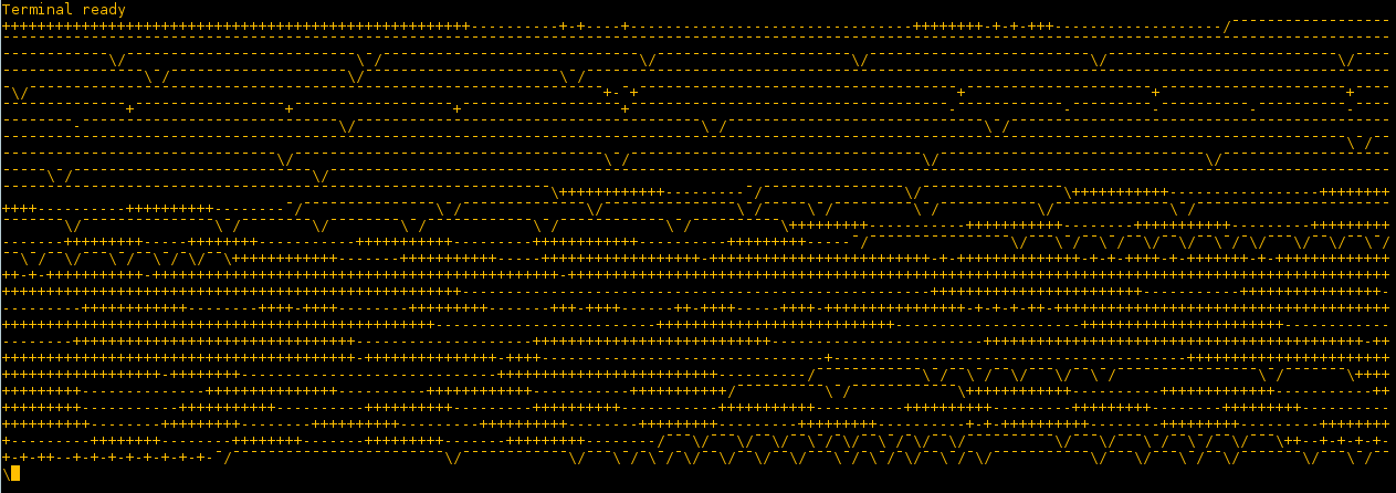
3 - Added an image showing terminal output.
2 -
1 - Initial project release
Add revision
blog comments powered by Disqus
Back


