-
Featured User: kurt

Open-source hardware project hosting is my passion. I spend most of my free time building neat gadgets or planning what I'll build next. I love building things, and I want to make Open Hardware Hub a place that inspires others to build, ...
-
Updates 2013 February 18
It's been a while, hasn't it? Well, that's ok because we've got a lot of updates to talk about. Most of these have been effective on the site fora couple weeks now. A few may or may not be active when this article gets posted, but they'll certainly be applied in the ...
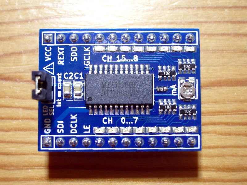
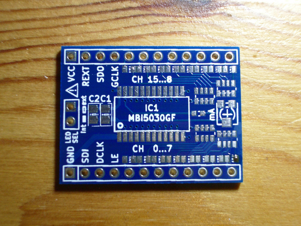
MBI5030 starter board


Files
This open source hardware project contains no files.
Bill of Materials
| Qty | Part # | Description | Schematic ID | Source | |
|---|---|---|---|---|---|
| 1 | MBI5030 | PWM LED-driver, 16-ch, SPI interface. | IC1 | Source | |
| 4 |
|
EXB-34V102JV | Res Thick Film Array 1K Ohm 5% ?200ppm/?C ISOL Molded 4-Pin 0606(2 X 0603) Convex SMD Punched Carrier T/R | Source | |
| 1 |
|
08055C104KAT2A | CAPACITOR, 0805, 0.1UF, 50V | Source | |
| 1 | GRM21BR61C475KA88L | CAPACITOR, 0805, X5R, 16V, 4.7UF | Source | ||
| 1 |
|
TC33X-2-202E | TRIMMER, 2K, 3MM | Source | |
| 16 |
|
SML-310MTT86 | SML-310 Series Green 0603 16 mcd Tinted Clear 2.2 V LED Surface Mount | Source |
Download BOM w/o images
Download BOM w/ images
Steps
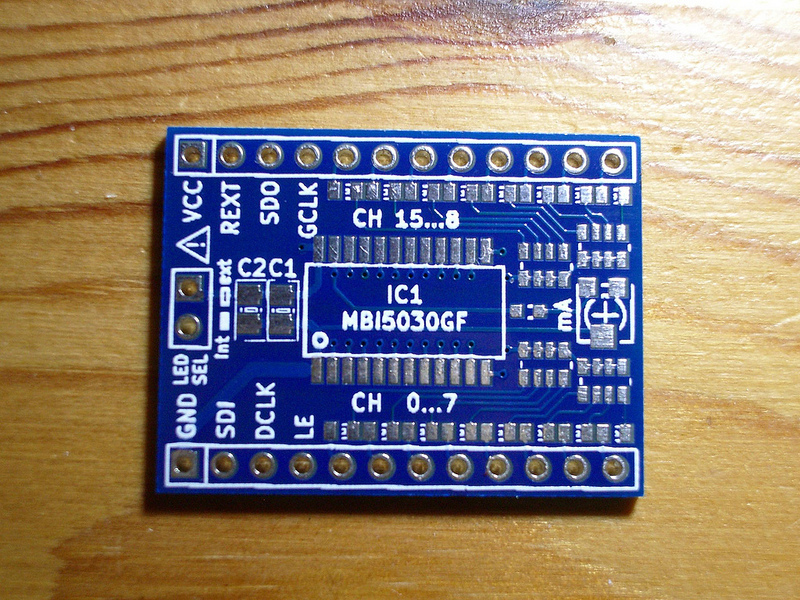
3. The back-side holds the key information
There should be markings... some kind of symbol. Don't assume anything, measure which way they should be placed. Then make the connection with the symbol.
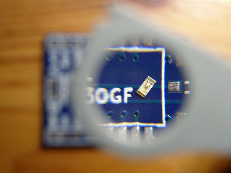
4. Starting with hand soldering
Place one bead of solder. Use flux.
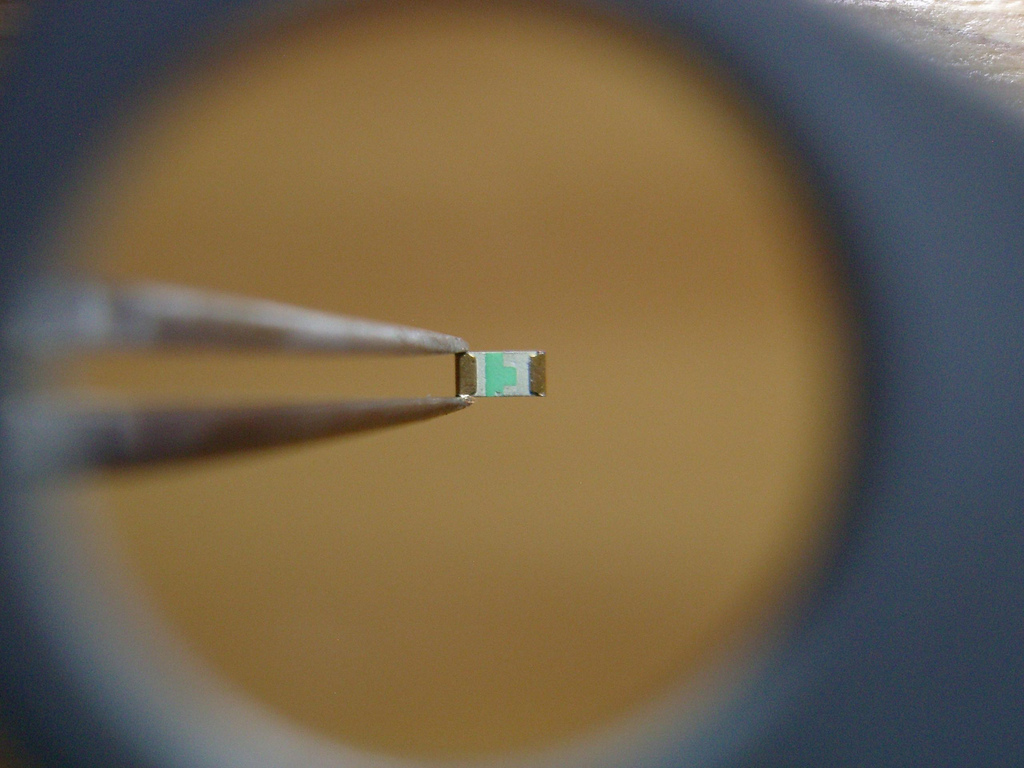
The LEDs are tiny, so you do need a small pointed tip to get inbetween them.
Download steps w/o images
Download steps w/ images
Revisions
3 - More descriptive project description.
2 - Added a link to tindie.
1 - Initial project release
Add revision
blog comments powered by Disqus
Back


