-
Featured User: kurt

Open-source hardware project hosting is my passion. I spend most of my free time building neat gadgets or planning what I'll build next. I love building things, and I want to make Open Hardware Hub a place that inspires others to build, ...
-
Updates 2013 February 18
It's been a while, hasn't it? Well, that's ok because we've got a lot of updates to talk about. Most of these have been effective on the site fora couple weeks now. A few may or may not be active when this article gets posted, but they'll certainly be applied in the ...
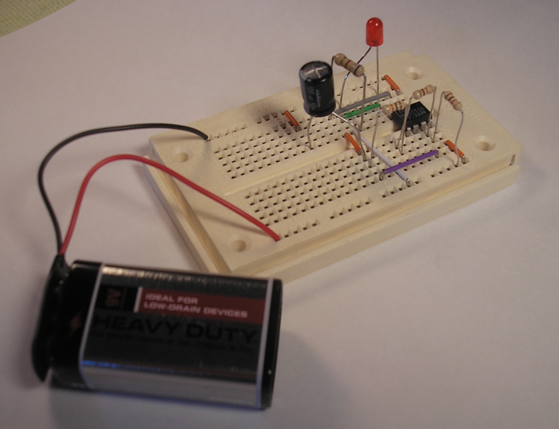
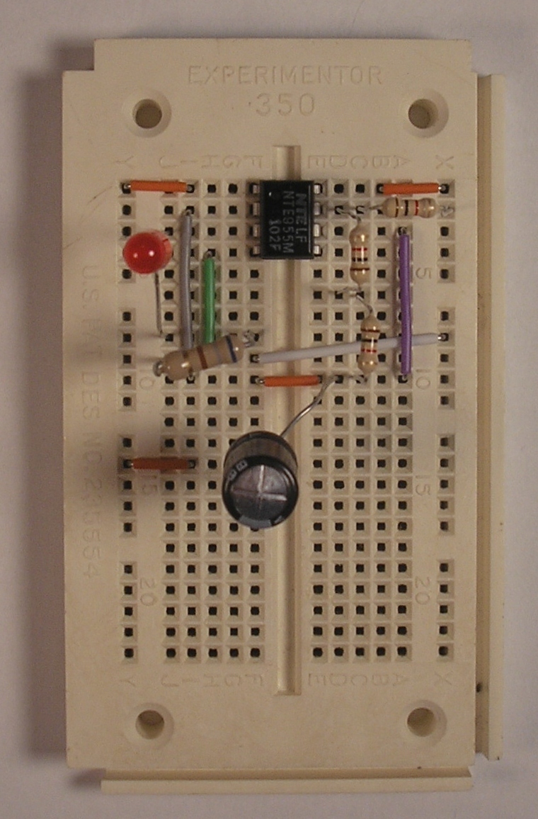
Blinking LED
Files
Bill of Materials
This open source hardware project contains no parts.
Steps
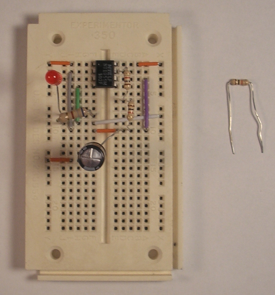
. Insert 2k resistor
Next, insert two 1k resistors in series between the positive lead of the capacitor and pin 7 of the 555 timer. Since these two resistors are in series, their resistances add and they are equal to one 2k resistor. Alternately, you can insert a single 2k resistor instead.
. Plug in 9V battery
Plug in the 9V battery, connect the black wire to the ground rail and the red wire to the +9V rail. Enjoy your blinking light!

Download steps w/o images
Download steps w/ images
Revisions
13 - fixed a typo
12 -
11 -
10 - changed LED part
9 - added project image description.
8 - changed 9V connector part added file descriptions
7 -
6 -
5 -
4 - updated parts so they have images now.
3 - added parts
2 - deleted missing step image. added parts. updated schematic.
1 -
Add revision
blog comments powered by Disqus
Back


