-
Featured User: kurt

Open-source hardware project hosting is my passion. I spend most of my free time building neat gadgets or planning what I'll build next. I love building things, and I want to make Open Hardware Hub a place that inspires others to build, ...
-
Updates 2013 February 18
It's been a while, hasn't it? Well, that's ok because we've got a lot of updates to talk about. Most of these have been effective on the site fora couple weeks now. A few may or may not be active when this article gets posted, but they'll certainly be applied in the ...
Blinking LED

Files
- Blinking_LED.sch - Blinking LED EAGLE Schematic
- Blinking_LED.pdf - Blinking LED PDF Schematic
Bill of Materials
| Qty | Part # | Description | Schematic ID | Source | |
|---|---|---|---|---|---|
| 1 |
|
NE555N | IC, TIMER | IC1 | Source |
| 1 |
|
ECA1EHG101 | CAPACITOR, 100UF, 25V | C1 | Source |
| 1 |
|
BS6I | SNAPS 9V 6" LEADS I-STYLE | 9V_BATTERY_CONNECTOR | Source |
| 1 |
|
CF14JT1K00 | 1/4w 1K ohms 5% Carbon Film Resistors | R1 | Source |
| 1 |
|
CF14JT2K00 | RES 2K OHM 1/4W 5% CARBON FILM | R2 | Source |
| 1 |
|
CF14JT470R | RES 470 OHM 1/4W 5% CARBON FILM | R3 | Source |
| 1 |
|
WP7113LID | 5MM LOW CURRENT RED LED, LAMP THOLE, BULK | LED1 | Source |
Download BOM w/o images
Download BOM w/ images
Steps
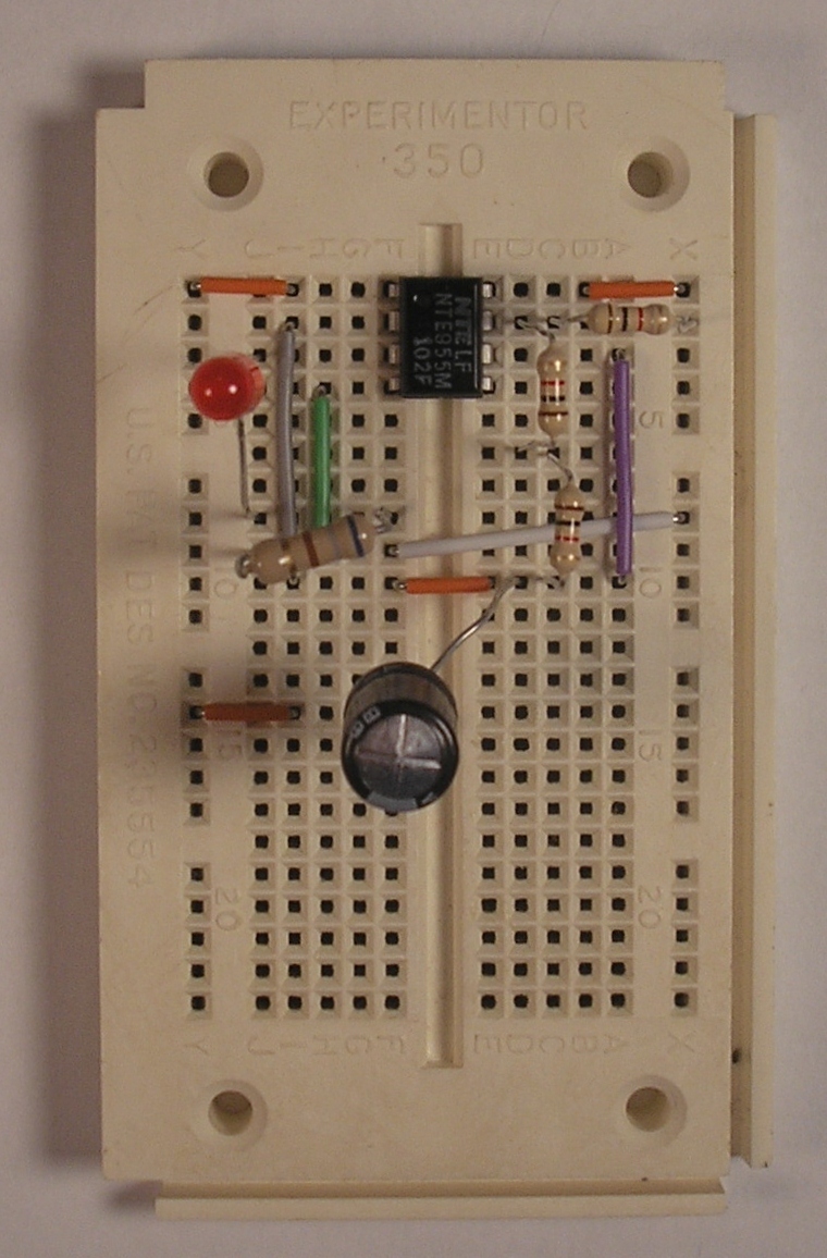
6. Insert 2k resistor
Next, insert two 1k resistors in series between the positive lead of the capacitor and pin 7 of the 555 timer. Since these two resistors are in series, their resistances add and they are equal to one 2k resistor. Alternately, you can insert a single 2k resistor instead.
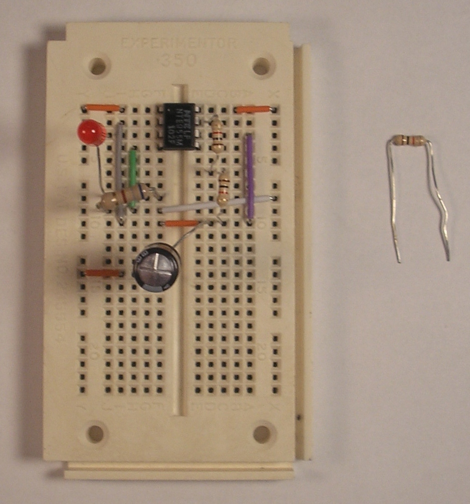
7. Insert 1k resistor
Install the final 1k resistor between pin 7 of the 555 timer and the +9V rail.
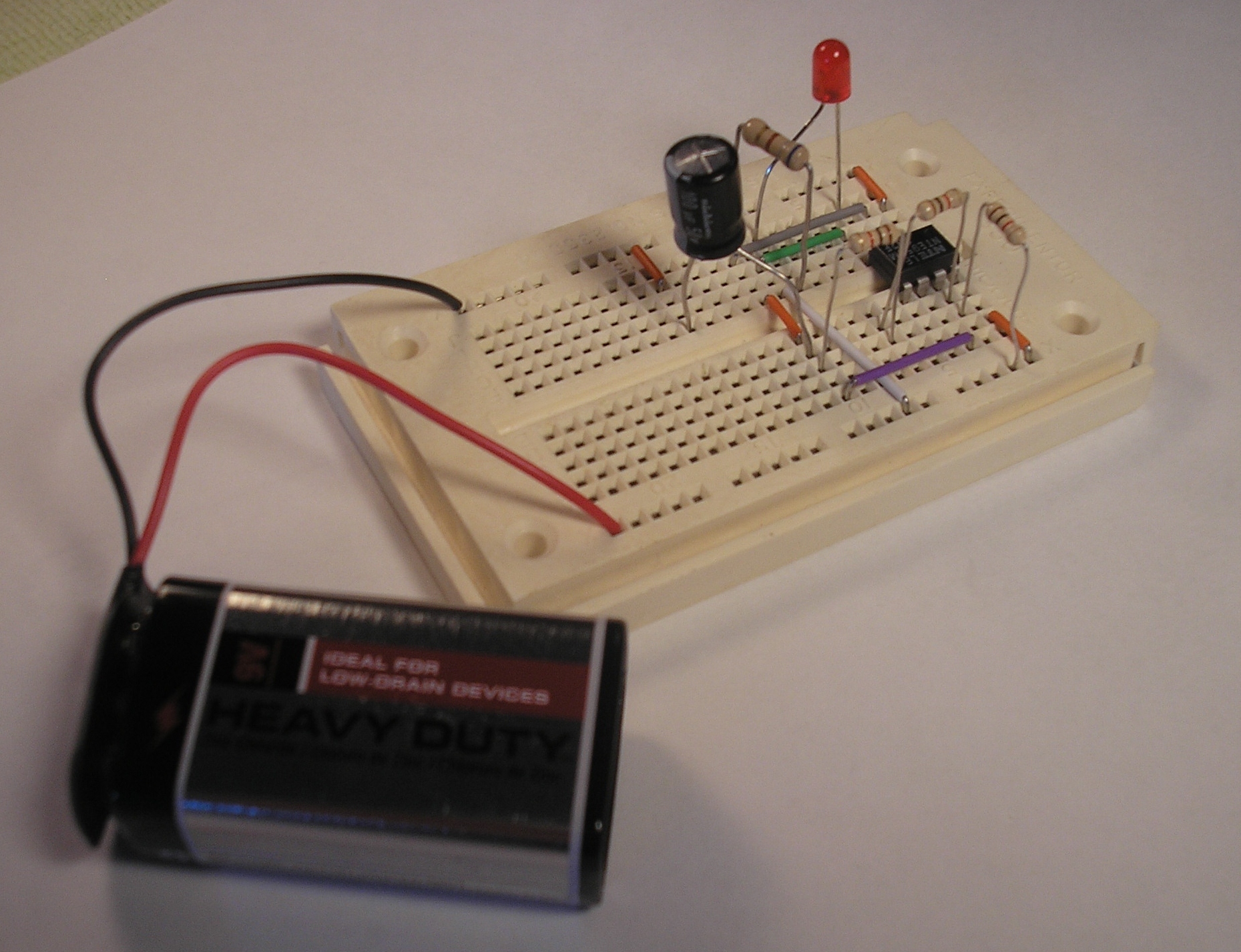
8. Plug in 9V battery
Plug in the 9V battery, connect the black wire to the ground rail and the red wire to the +9V rail. Enjoy your blinking light!
Download steps w/o images
Download steps w/ images
Revisions
13 - fixed a typo
12 -
11 -
10 - changed LED part
9 - added project image description.
8 - changed 9V connector part added file descriptions
7 -
6 -
5 -
4 - updated parts so they have images now.
3 - added parts
2 - deleted missing step image. added parts. updated schematic.
1 -
Add revision
blog comments powered by Disqus
Back


