-
Featured User: kurt

Open-source hardware project hosting is my passion. I spend most of my free time building neat gadgets or planning what I'll build next. I love building things, and I want to make Open Hardware Hub a place that inspires others to build, ...
-
Updates 2013 February 18
It's been a while, hasn't it? Well, that's ok because we've got a lot of updates to talk about. Most of these have been effective on the site fora couple weeks now. A few may or may not be active when this article gets posted, but they'll certainly be applied in the ...
A lamp for nerds


Files
- schematic.pdf - schematic
- kitchen_lights.cbp - Code::Blocks IDE project file
- system_ticker.c - system_ticker interrupt
- system_ticker.h - sysem_ticker interrupt
- spi.c - SPI interface
- spi.h - SPI interface
- status_leds.c - status LEDs
- status_leds.h - status LEDs
- button.c - read buttons
- button.h - read buttons
- led_driver.c - LED driver handling
- led_driver.h - LED driver handling
- uart.c - inter board communication UART
- uart.h - inter board communication UART
- main.c - main program
- main.h - main program
- Makefile - makefile
- ATtiny2313.hex - precompiled firmware
- flash.sh - upload BASH script
- README.TXT -
- code_and_docs.zip - Archive
Bill of Materials
| Qty | Part # | Description | Schematic ID | Source | |
|---|---|---|---|---|---|
| 1 |
|
ATTINY2313-20SU | IC, 8BIT 2K FLASH MCU, 2313, SOIC20 | IC1 | Source |
| 1 | MBI5168 | 8-channel constant current LED driver with SPI interface. Pin compatible with STP08CP05, but cheaper | IC2 | Source | |
| 1 |
|
L78L05CD | IC, V REG +5.0V, SMD, 78L05, SO-8-8 | IC3 | Source |
| 15 |
|
ERJ-3EKF1001V | RESISTOR, 0603, 0.1W, 1%, 1K | R3-R17 | Source |
| 1 |
|
ERJ-3EKF1002V | RESISTOR, 0603, 0.1W, 1%, 10K | R1 | Source |
| 6 |
|
ERJ3EKF4700V | RESISTOR, 0603, 0.1W, 1%, 470R | R18-23 | Source |
| 1 |
|
HSMC-C170 | LED, SMD, RED | D36 | Source |
| 1 |
|
HSMG-C170 | LED, GREEN, 15MCD, 572NM | D37 | Source |
| 1 |
|
HSMR-C170 | LED, SMD, BLUE | D38 | Source |
| 2 |
|
HSMY-C170 | LED, SMD, YELLOW | D34-D35 | Source |
| 1 |
|
SSL-LX3044LGD | LED, 3MM, GREEN, 30MCD, 565NM | D33 | Source |
| 2 |
|
08055C104KAT2A | CAPACITOR, 0805, 0.1UF, 50V | C1, C3 | Source |
| 4 |
|
GRM31CR61E106KA12L | CAPACITOR, 1206, X5R, 25V, 10UF | C2, C4-C6 | Source |
| 2 |
|
ECA1VHG102 | CAPACITOR, 1000UF, 35V | C7, C8 | Source |
| 1 |
|
CB10LV471M | TRIMMER, TOP ADJUST, 470R | RV1 | Source |
| 1 |
|
929550-01-36-I | HEADER, PIN, 36WAY | JP2 | Source |
| 1 |
|
929836-01-36 | Pin Strip Header | JP1, P1, P2 | Source |
| 3 |
|
PTS645SL43 LFS | TACTILE SWITCH | SW1-SW3 | Source |
| 32 |
|
NSPWR70CSS-K1 | Nichia NSPWR70CSS Superflux LED, white, 20lm @ 50mA, 129lm/W | D1-D32 | Source |
| 1 |
|
MDR-40-12 | PWR SPLY,SW,40W,12V/3.33A,DIN, 85-264VAC,UL/CB/TUV/CE/CUL | Source | |
| 1 | FL22 | FLUX, SMD, 5ML | Source | ||
| 1 |
|
24-6337-0010 | 44 Series Wire Solder | Source |
Download BOM w/o images
Download BOM w/ images
Steps
6. Make it all work
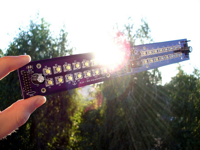
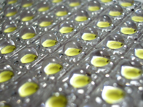
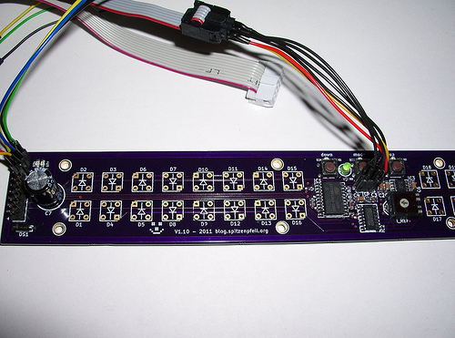
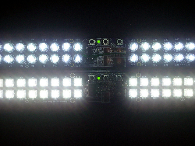
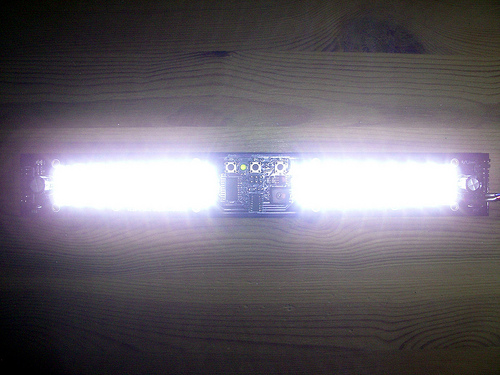
The lamp itself is simple. There are 32 LEDS grouped in 8 channels (because the LED driver has 8 channels). Each board totals to about 6W and 600 lumen.
If you like, you can think of the driver as a simple 8-bit shift register, but with integrated constant current control. Anybody can talk to shift registers using SPI ;-)
The switch-mode power supply is chosen such that it feeds the LED driver with a voltage slightly above what 4 LEDs in series need, which is about 13.5V give or take. The power supply is nominally 12V, but can be adjusted with a trimmer from about 11-15V. This is essential, as the LED driver is not a switch-mode one, but a simple linear device. Feed it with too much voltage and it literally burns.
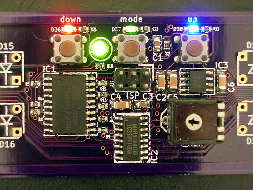
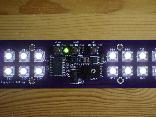
Brightness is regulated by a hardware PWM pin of the ATtiny2313, which is wired to the enable pin of the LED driver. 3 buttons are used to talk to the lamp. Certain combinations of presses trigger either local or, if more than 1 lamp is used, remote actions.
Inter-lamp-communication uses the hardware UART in half-duplex mode, using just a single shared signal line. The local echo is suppressed by intelligent programming. Several status LEDs indicate button presses and sent/received commands. Per default each lamp on the bus starts up as a listener. Only when data is in the transmit buffer of a lamp, it switches to 'master' and sends out data. There could be collisions, but usually the user only presses a button on one lamp at any given time. As I've heard of Murphy's Law as well, all I/O pins of the ATtiny2313 are protected with 1k resistors, which makes them short-circuit resistant.
Code is uploaded to the micro-controller with a standard ISP programmer like e.g. an usbtiny, which also happens to be very affordable. Speaking of affordable... this is definitely not the cheapest way to use LEDs for serious illumination, but making is part of the fun. And these boards will probably last forever.
3 of those lamps are used to illuminate the working area in my kitchen, which I will not show here ;-)
Download steps w/o images
Download steps w/ images
Revisions
4 -
3 - Added all design files.
2 - Fixed a typo.
1 - Initial project release
Add revision
blog comments powered by Disqus
Back


