-
Featured User: kurt

Open-source hardware project hosting is my passion. I spend most of my free time building neat gadgets or planning what I'll build next. I love building things, and I want to make Open Hardware Hub a place that inspires others to build, ...
-
Updates 2013 February 18
It's been a while, hasn't it? Well, that's ok because we've got a lot of updates to talk about. Most of these have been effective on the site fora couple weeks now. A few may or may not be active when this article gets posted, but they'll certainly be applied in the ...
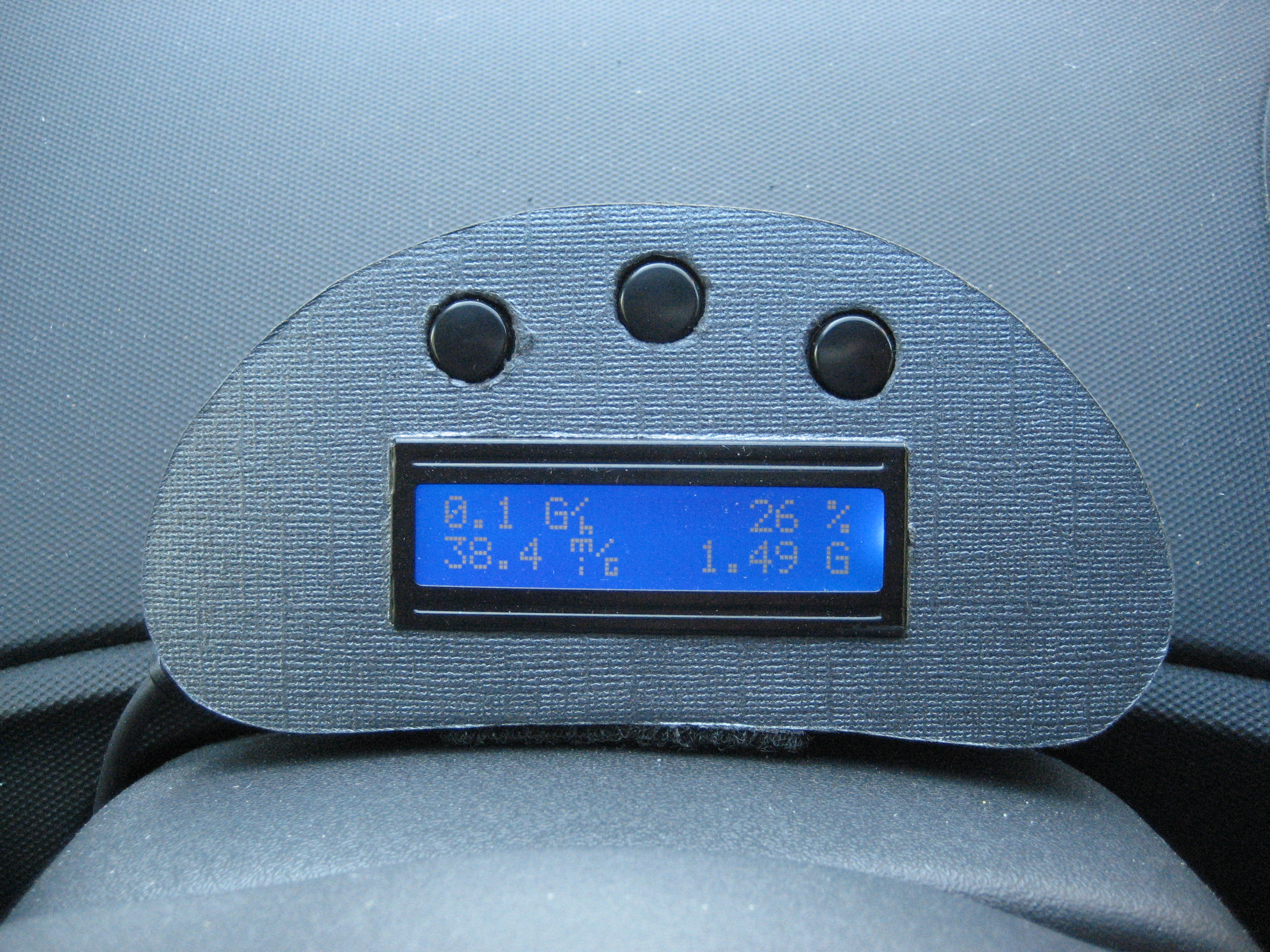
Arduino CAN-BUS OBD Gas Gauge

Files
- canbus.brd - Eagle Board file
- canbus.sch - Eagle schematic file
- MCP2515.rar - MCP2515 Arduino Library
- OBDIICanbus.rar - OBDII CAN-BUS library
- obduino32K_with_buttons.ino - OBDII Can Bus main code
Bill of Materials
| Qty | Part # | Description | Schematic ID | Source | |
|---|---|---|---|---|---|
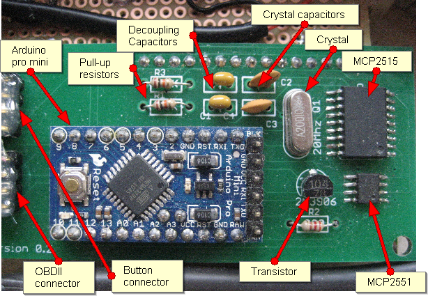
| 1 | MCP2551 | High-speed CAN Transceiver | |||
| 1 | MCP2515 | Stand-Alone CAN Controller with SPI Interface | |||
| 1 |
|
Arduino Pro Mini 328 | It's blue! It's thin (0.8mm)! It's the Arduino Pro Mini! SparkFun's minimal design approach to Arduino. This is a 5V Arduino running the 16MHz bootloader (select 'Arduino Duemilanove w/ 328' within the Arduino software). | Source | |
| 1 |
|
OBDII Connector - | OBD2 OBDII EOBD J1962 Connector Adaptor - Right Angle | Source | |
| 2 | 0.1uF Capacitor | 0.1uF Capacitor | Source | ||
| 2 | 22pF Capacitor | 22pF Capacitor | Source | ||
| 2 | 1/4W 5% 10K Resistor | 1/4W 5% 10K Resistor - Generic from Radio Shack | |||
| 1 | 1/4W 5% 220 Resistor | 1/4W 5% 220 Resistor - Generic from Radio Shack | |||
| 1 | 2N3906 | Transistor - Generic from Radio Shack | |||
| 1 |
|
LCD | Standard LCD 16x2 + extras - white on blue Has header pins and potentiometer | Source | |
| 3 |
|
switch | Tactile & Jog Switches TACT SWITCH 12X12MM | Source | |
| 3 |
|
cap | Switch Hardware 12X12 RND BLK CAP - This one is black but other colors are available. | Source | |
| 2 |
|
Pin Header | Break-away 0.1" 36-pin strip male header | Source | |
| 1 |
|
Crystal | Crystal 20 MHZ | Source | |
| 1 |
|
enclosure | Build your own or buy an enclosure. | ||
| 2 |
|
Pin Header | Headers & Wire Housings R/A PCB HDR 4P TIN FRICTION LOCK | Source | |
| 2 |
|
Female Pin Header | Headers & Wire Housings HSG 4P WITH LKG RAMP | Source | |
| 8 |
|
Crimp Terminal | .100" CRIMP TERMINALS | Source | |
| 1 | cable (3 ft) | 4 core 22 awg stranded cable. Taken from an old broken keyboard. | |||
| 1 |
|
FTDI Basic breakout | FTDI Basic Breakout - 5V | Source | |
| 1 | Circuit Board | Circuit Board - Custom Circuit Board, sized to match the LCD circuit board size. See attached Eagle files for details. |
Download BOM w/o images
Download BOM w/ images
Steps
1. Make sure your card supports CAN-BUS
Please make sure that your car supports CAN-BUS protocol. Not all cars do, especially older cars, before 1998, but more and more newer cars do. Two cars I know for sure do:
1996 Scion Xa and
2011 Nissan Versa (Father in-law had a rental).
A site that might help with determining this is: http://www.auterraweb.com/aboutcan.html
2. Gather parts
I have tried to link to as many parts as I could in the parts list. Some are from eBay, some from Radio Shack and even got my cable from Goodwill from a used keyboard for a couple of bucks.
Sparkfun for the Arduino and Mouser for the remaining parts.
Thiss was the first time I have designed a circuit board and the first time I have used Eagle CAD. I relied on the auto-routing features and I am sure the more experienced designers will be gasping in horror at my board. But it works and that is good enough for me. The circuit board was ordered from Sparkfun spinoff site at http://batchpcb.com/index.php/Home.
I sincerely apologize for the lack of steps detailing how to solder all the parts into place and images. I did not think that I would be detailing the process. My bad.
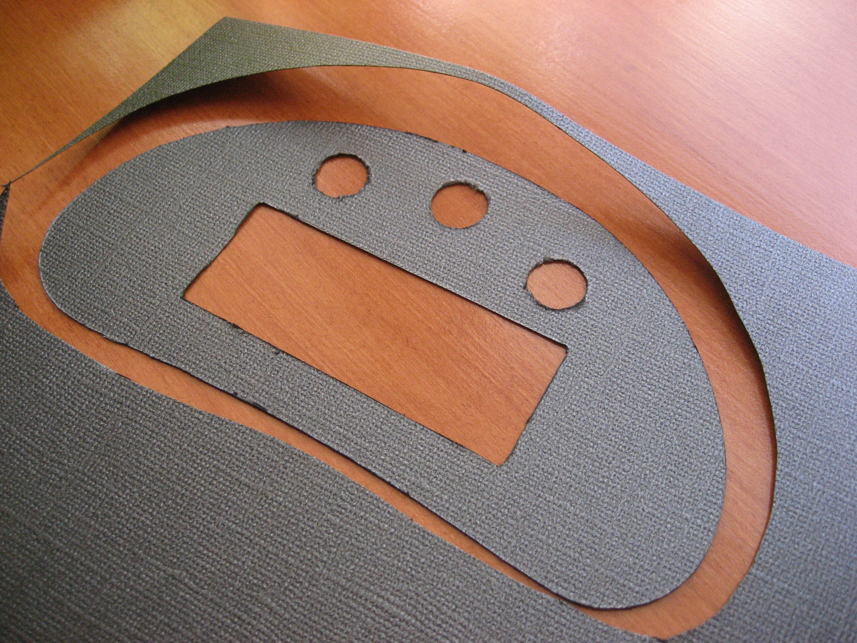
3. Build enclosure
This is one of the hardest parts of this project. I did some extensive searching for a project enclosure. None of them fitted my needs. I even considered a glasses case. Eventually I decided that I would have to resort to building my own.
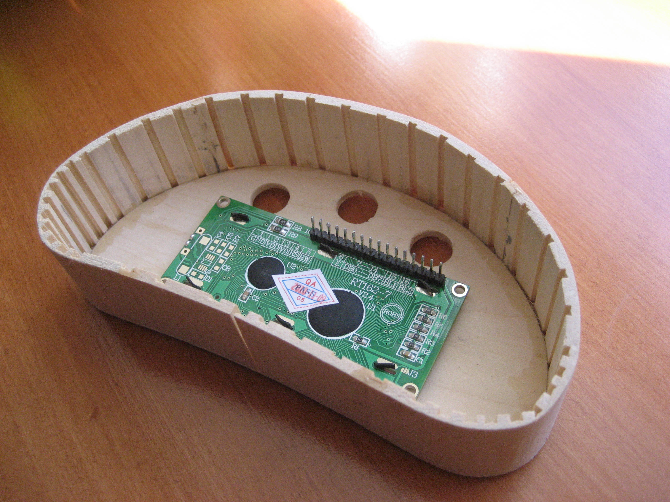
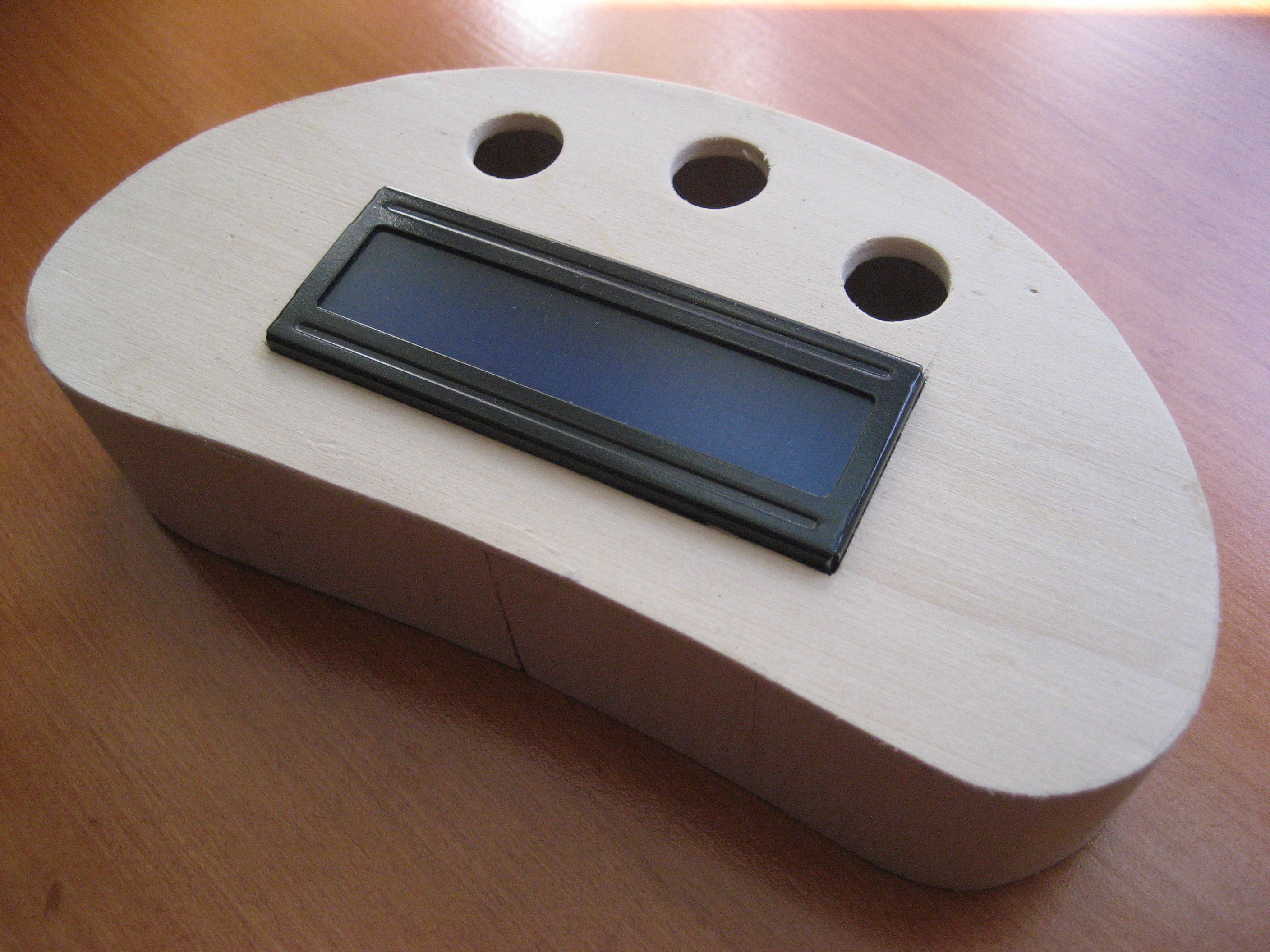
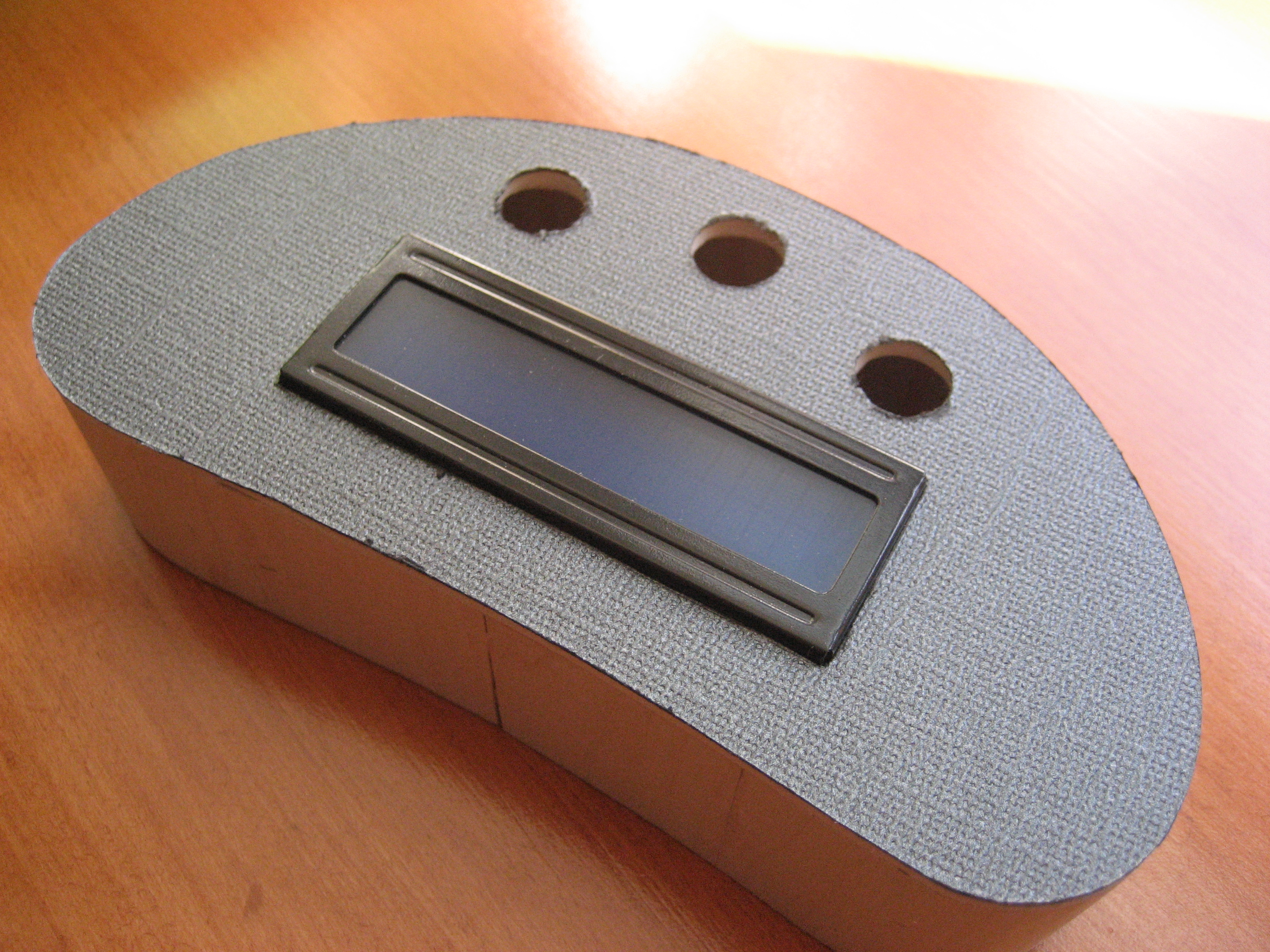
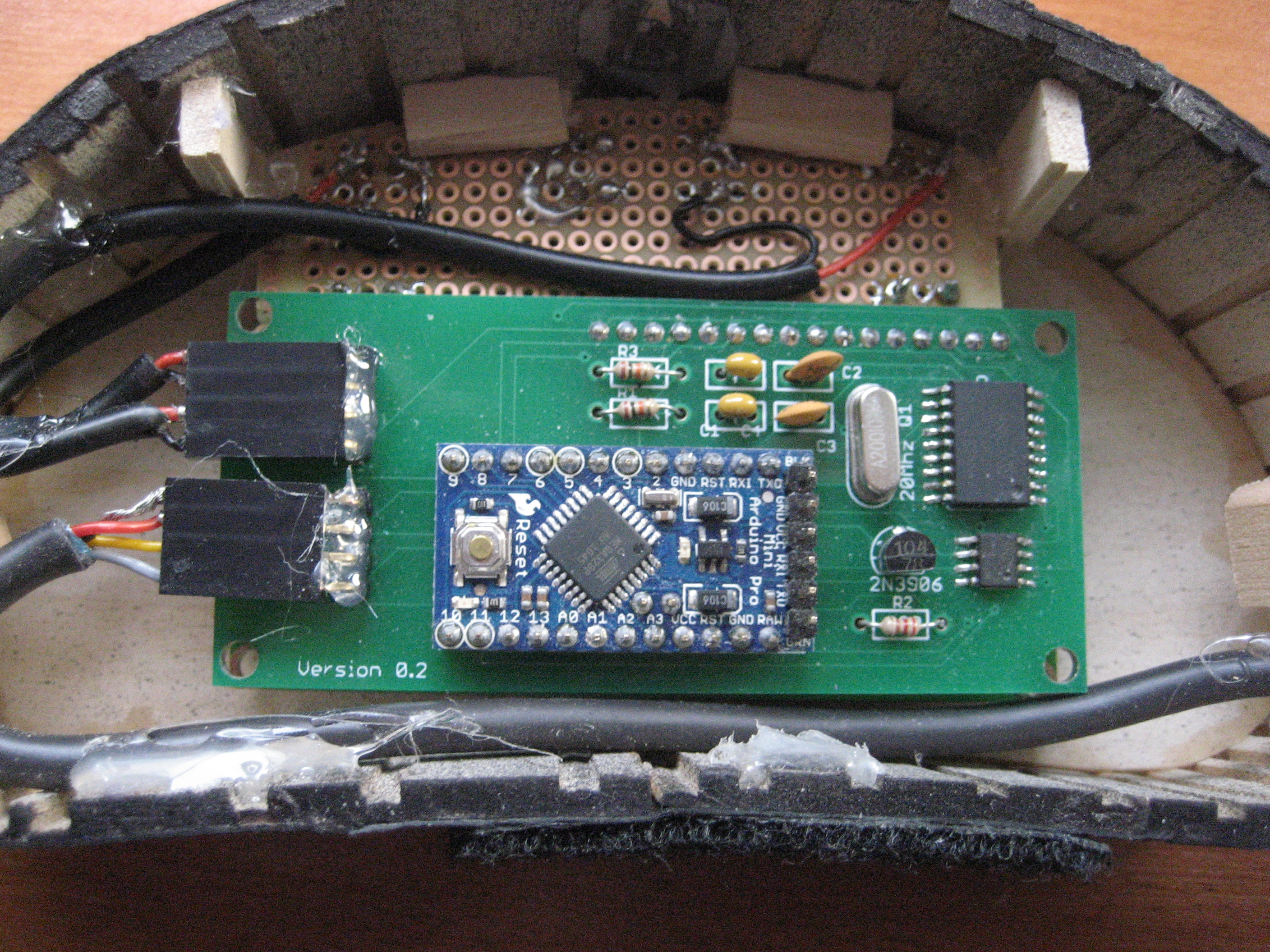
I bought Bass wood from local hardware store (Ace or Michaels) and using a coping saw and a table saw to make kerf cuts, so I could bend the wood, I came up with the "kidney bean" design shown. The image shows the LCD placed inside the enclosure. My circuit board is soldered directly to the LCD header pins.
The gray textured finish is actually paper from Michaels scrapbook section. They have some pretty cool paper with all sorts of finishes. Cut out using sharp knife and glued directly to the enclosure.
4. Solder parts
Some parts are surface mount and there are plenty of examples on YouTube on how to do this so I will not be going into details.
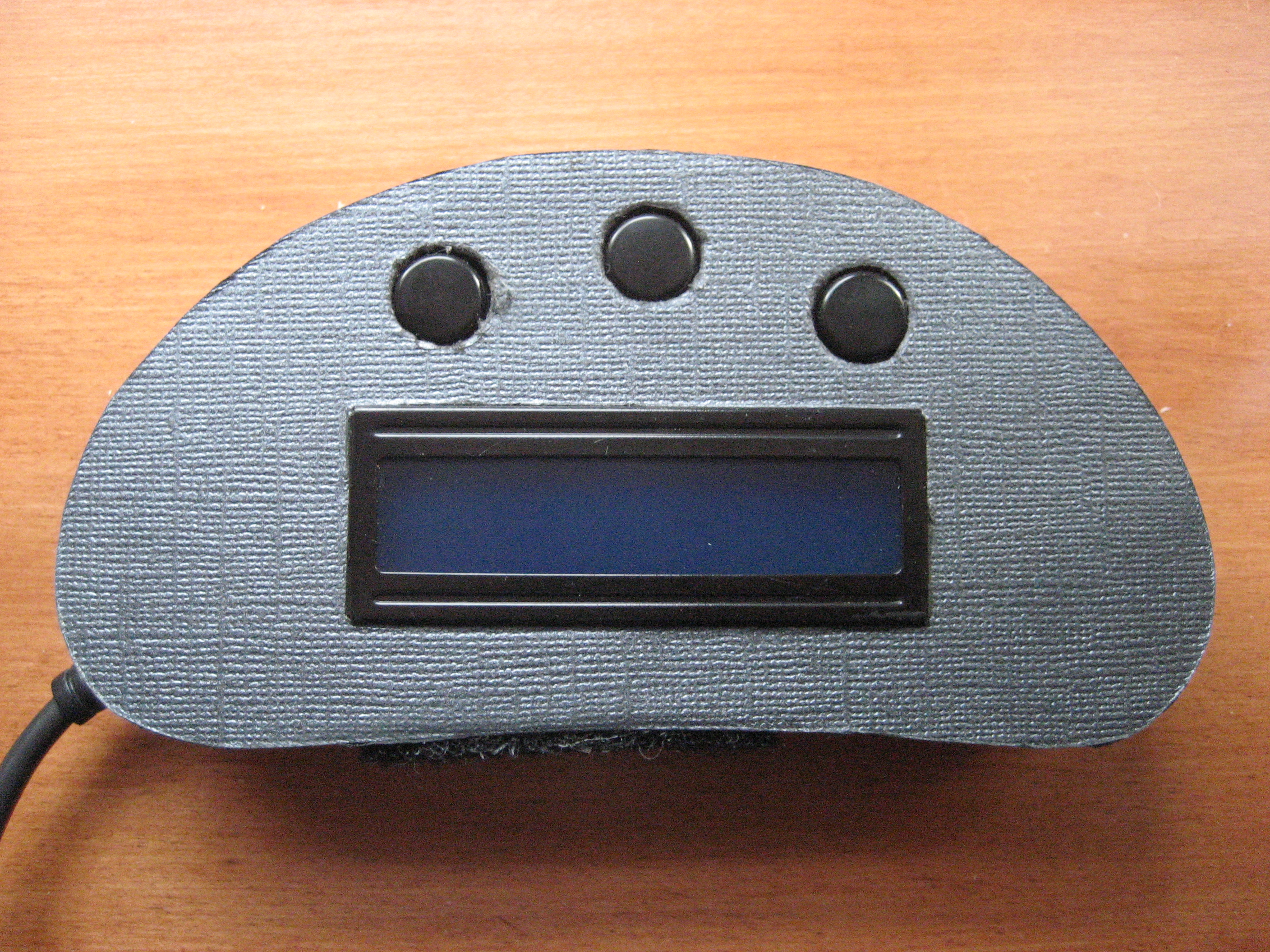
The circuit board I designed was sized to be exactly the same size as the LCD and is soldered to the 16 header pins from the LCD. The 3 buttons were soldered directly to a piece of protoboard from Radio Shack and then wired to female header for connection to the circuit board. I mounted the buttons into the enclosure with scraps of wood and a hot glue gun. See the "fit into enclosure" section for photo.
5. Build the OBDII cable
The cable I used came from an old keyboard that I found at Goodwill. One end it attached to the J1962 (OBDII port) and the other end to the Female Pin Header. The connections is are:
GND ->4,
RAW ->16,
CANL->14,
CANH->6,
For more information on the OBDII port and its pin connections see the following URL: http://www.obd2cables.com/products/obd-cables/cable-j1962m-to-db9f-type-d-6ft.html
Download steps w/o images
Download steps w/ images
Revisions
1 - Initial project release
blog comments powered by Disqus
Back


