-
Featured User: kurt

Open-source hardware project hosting is my passion. I spend most of my free time building neat gadgets or planning what I'll build next. I love building things, and I want to make Open Hardware Hub a place that inspires others to build, ...
-
Updates 2013 February 18
It's been a while, hasn't it? Well, that's ok because we've got a lot of updates to talk about. Most of these have been effective on the site fora couple weeks now. A few may or may not be active when this article gets posted, but they'll certainly be applied in the ...
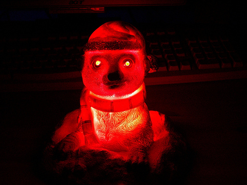
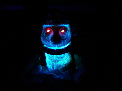
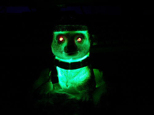
Zombie Meerkat


Files
- blinky-eyes_code.zip - code
- blinky-eyes_schematic.jpg - schematic
Bill of Materials
| Qty | Part # | Description | Schematic ID | Source | |
|---|---|---|---|---|---|
| 1 |
|
22-518 | GC ELECTRONICS 22-518 3 3/4" x 8" Perforated Bare Phenolic Prototype Board Ideal for prototypes, breadboards, hobby or science projects. Made of durable phenolic with punched holes. Boards are bare phenolic - no copper clad. | Source | |
| 1 |
|
RN55D1002FB14 | METAL FILM RESISTOR | Source | |
| 1 |
|
167104J100A-F | Film Capacitor | Source | |
| 1 |
|
RNF18FTD294R | RES 1/8W 294 OHM 1% AXIAL | Source | |
| 1 |
|
CB10LV471M | TRIMMER, TOP ADJUST, 470R | Source | |
| 1 |
|
929836-01-36 | Pin Strip Header | Source | |
| 1 |
|
ATTINY24-20PU | AVR MCU, 2K FLASH, 128B RAM, DIP14 | Source | |
| 1 | MBI5168 DIP | 8-channel constant current LED driver with SPI interface. Pin compatible with STP08CP05, but cheaper | Source | ||
| 1 |
|
MCDL-5013RGBC-TL-A | LED,RGB,WATER CLEAR,T1-3/4,2.0 -3.5VF@20mA,COMMON ANODE,25DE | Source |
Download BOM w/o images
Download BOM w/ images
Steps
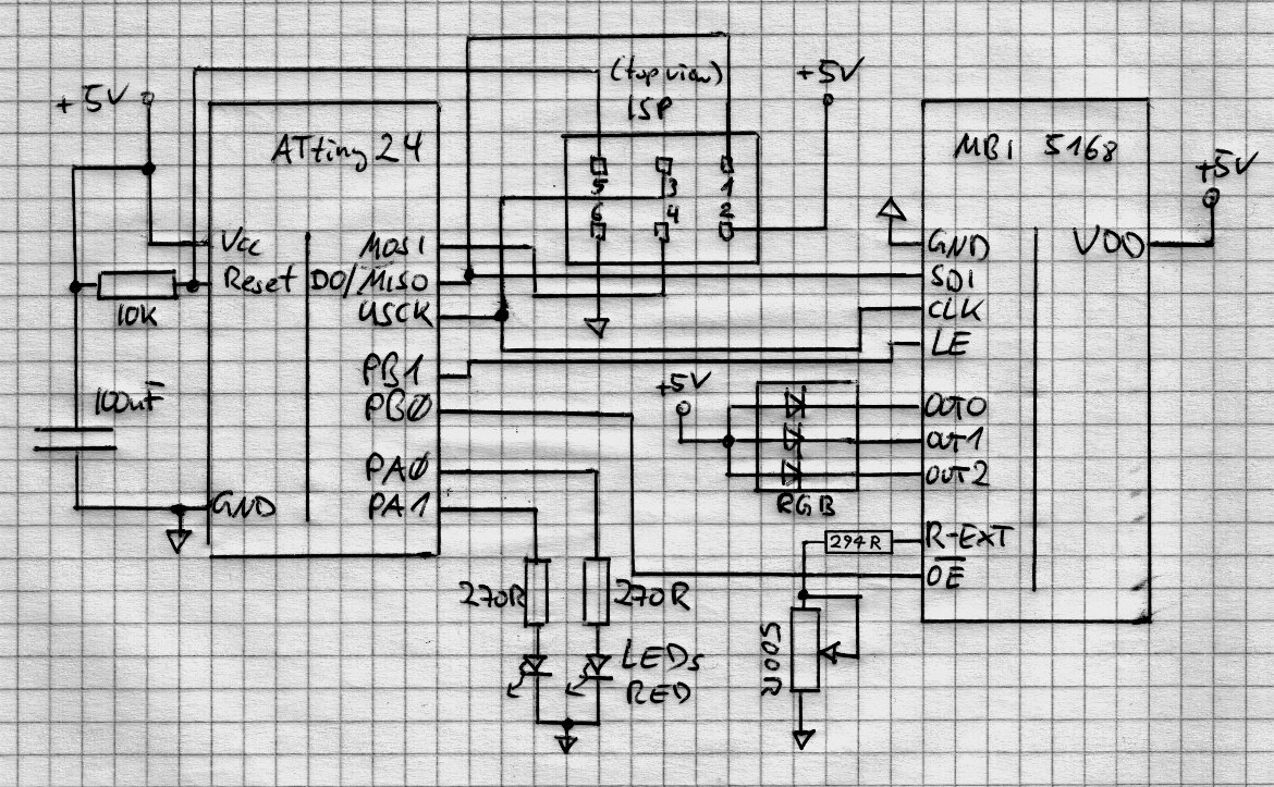
1. Schematic
The ATtiny24 side of the project is just the bare minimum to get the chip going. It consists of a 10k pull-up resistor for the RESET line, the ISP header for programming and a 100nF capacitor on the supply lines. Adding some more capacitance with an electrolytic capacitor doesn't hurt. The LED driver chip would benefit from some capacitance on its supply lines as well. It shares some I/O lines on the ATtiny24 with the ISP header. The common anode RGB LED connects directly to 5V and the individual cathodes go into the chip. A 500R potentiometer is used to adjust the current output of the driver. The 294R resistor limits the maximum current. I assume you have blank chip running on the internal RC oscillator, no external quartz needed. The FUSE settings for running at 8MHz can be found in the code zip-file ('flash.sh').

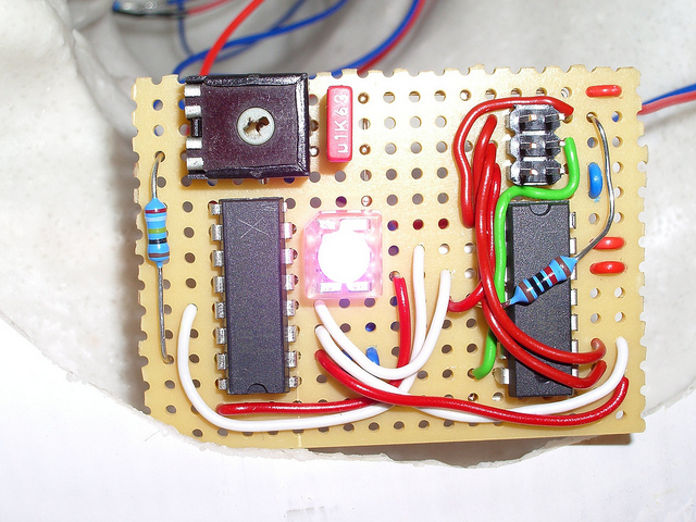
2. Assemble
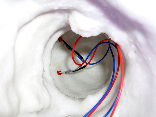
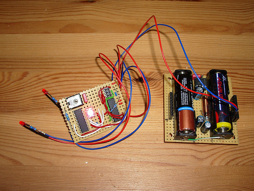
Get some decent solid core wire for the connections on the perfboard. If you have a choice, make sure the insulation doesn't melt too easily. Take a look at the datasheets of both the ATtiny24 and the MBI5168 chips and try to arrange them on the perfboard optimally. If you have differently colored wire use it. Start with the ATtiny24 side, add the ISP header, 10k resistor and the 2 red LEDs (use long wires, so you can move them to where the eyes are) and power connections. Use an ISP programmer (e.g. usbtiny) to verify the chip is alive. ( avrdude -c usbtiny -p attiny24 -vvvvv ). You shouldn't get any error messages. Once that is verified to work, add the RGB LED and the driver chip + resistor + potentiometer. Take your time. Use hot-glue liberally to attach everything to the sculpture. Ideally you would use 3 AA cells to power the board, it will suck them dry ;-) If you have a 'mintyboost', giving you a nice 5V, use that!
3. Code
The main() part of it is very simple. It turns the 'eyes' on, waits a random amount of time, turns the eyes off again, waits a random amount of time and changes the hue of the RGB LED a tiny bit. Repeat. The supporting code provides the delay() function, PWM control of the LED and simple functions to change colors. Either use the Makefile or if you have 'Code::Blocks', use its project file (.cbp) to compile. Take a look at the 'flash.sh' file for FUSE settings and how to upload the firmware.
Download steps w/o images
Download steps w/ images
Revisions
1 - Initial project release
Add revision
blog comments powered by Disqus
Back


