-
Featured User: kurt

Open-source hardware project hosting is my passion. I spend most of my free time building neat gadgets or planning what I'll build next. I love building things, and I want to make Open Hardware Hub a place that inspires others to build, ...
-
Updates 2013 February 18
It's been a while, hasn't it? Well, that's ok because we've got a lot of updates to talk about. Most of these have been effective on the site fora couple weeks now. A few may or may not be active when this article gets posted, but they'll certainly be applied in the ...
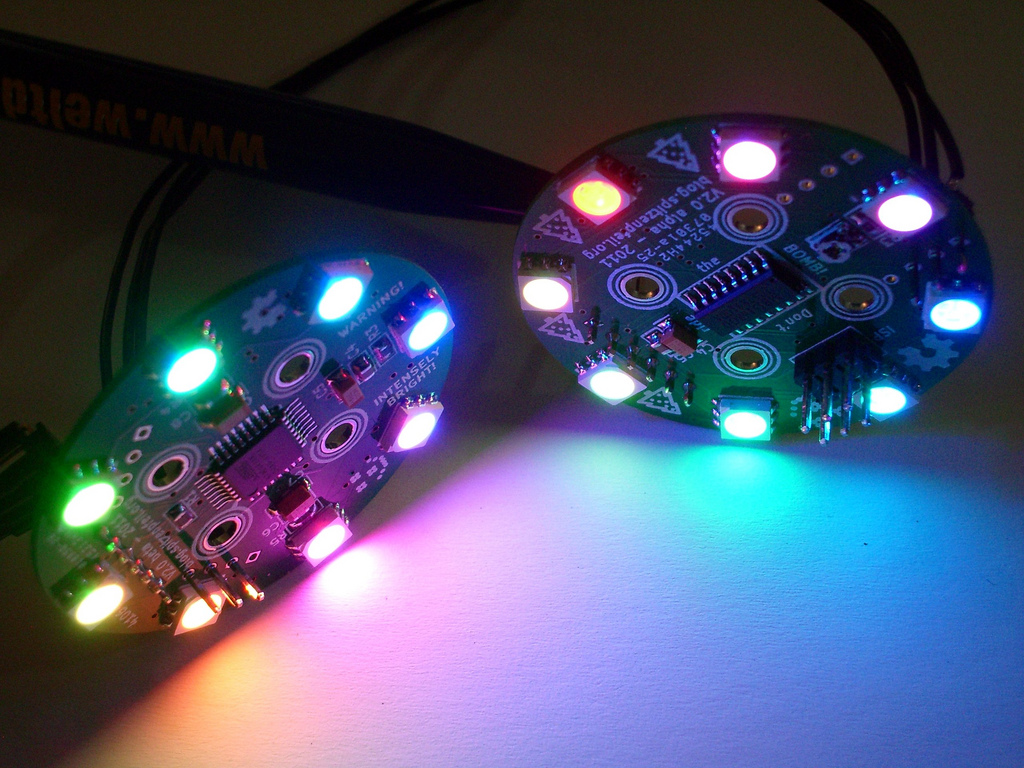
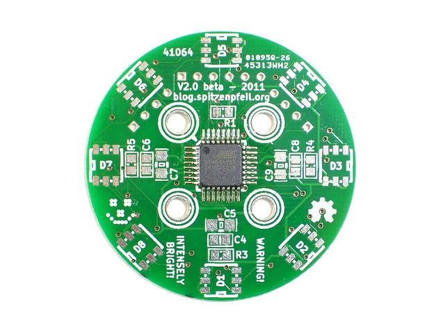
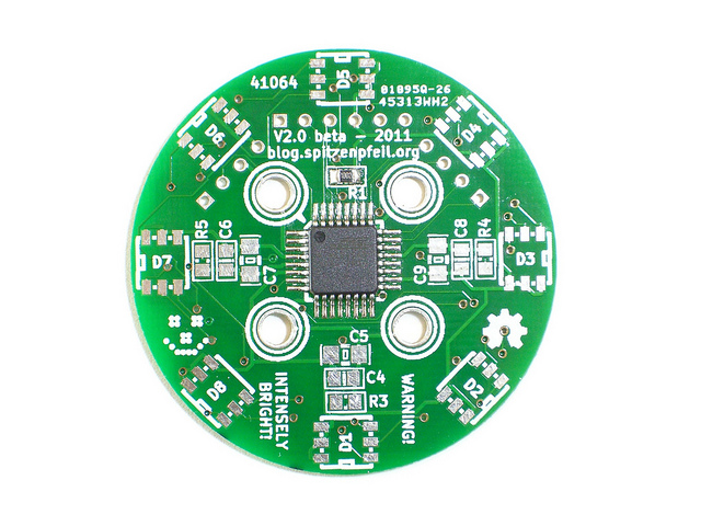
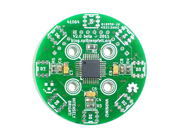
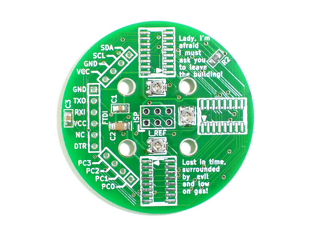
RGB LED RING V2

Files
- rgb_led_toy_test-4e481b6.zip - latest code snapshot
- RGB_LED_TOY-d903c76.zip - final board design-files
Bill of Materials
| Qty | Part # | Description | Schematic ID | Source | |
|---|---|---|---|---|---|
| 1 |
|
ATMEGA168-20AU | 8BIT 16K FLASH MCU, TQFP32, 168 | Source | |
| 3 |
|
STP08CP05MTR | STP08CP05 Series 100mA 30 MHz Low Voltage Low Current Power 8-bit Shift Register | Source | |
| 3 |
|
TC33X-2-202E | TRIMMER, 2K, 3MM | Source | |
| 3 |
|
CRCW0805560RFKEA | RESISTOR, 0805, 560R , 1% | R3-5 | Source |
| 2 |
|
CRCW080510K0FKEA | RESISTOR, 0805, 10KR , 1%,0.125W | R1-2 | Source |
| 8 |
|
VAOS-5050RGB-W1 | LED, RED / GREEN / BLUE, PLCC-6 | D1-8 | Source |
| 1 |
|
929836-03-36 | Pin Strip Header | JP1 | Source |
| 5 |
|
08055C104KAT2A | CAPACITOR, 0805, 0.1UF, 50V | C1, C3, C4, C6, C8 | Source |
| 1 |
|
1206YD106KAT2A | CAPACITOR, 1206, 10UF, 16V, X5R | C2 | Source |
| 3 |
|
B45196H3106K109V17 | CAP TANT 10UF 16V 10% 1206 | C5, C7, C9 | Source |
Download BOM w/o images
Download BOM w/ images
Steps
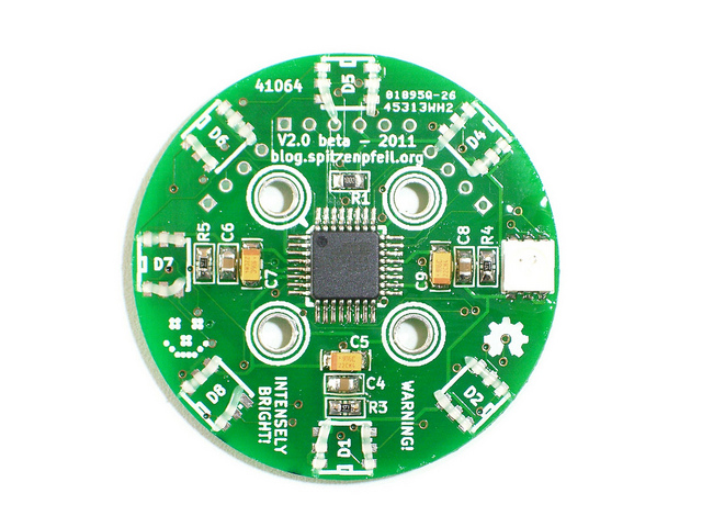
1. Solder the AVR chip
Apply a generous amount of paste flux across the pads on the board and place the chip. The dot on the chip should match the dot on the silkscreen. Adjust the position until the pins are well centered on the pads. Tack down the chip on 2 opposite sides and solder the remaining pins. Preferably use 0.5mm rosin core solder.
2. Pull-up resistors and decoupling caps
Apply flux to the board, place the part, apply a bit of solder to the clean tip of the iron, pin down the part with curved tweezers and solder one side. Solder the other side as usual and touch up the first joint if necessary.
R1, R2, C1, C2, C3


3. FUSE settings & bootloader
Now that all parts are soldered that are necessary to power up the microcontroller, let's do that. This will also tell if the thing is alive at all. The FUSE bits of the ATmega168 should be changed to these values:
LFUSE: 0xE2
HFUSE: 0xDD
EFUSE: 0x04
With 'avrdude' that looks like (one-liners!):
avrdude -c $PROGRAMMER -p atmega168 -B 100 -P $PORT -b $BAUDRATE -e -U lock:w:0x3F:m -U lfuse:w:0xE2:m -U hfuse:w:0xDD:m -U efuse:w:0x04:m
avrdude -c $PROGRAMMER -p atmega168 -B 1 -P $PORT -b $BAUDRATE -U flash:w:optiboot_pro_8Mhz.hex -U lock:w:0x0F:m
Replace all $-variables with ones suitable to what You have. The bootloader hex file can be found in the Arduino IDE 1.0 folders.
If this step succeeds without error messages, we can continue with the remaining parts.
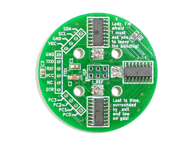
4. LED drivers
Solder the SO-16 chips the same way as the microcontroller: flux, orientation, tack down, solder remaining pins.
The parts list shows the STP08CP05, whereas the schematic in the zip-file shows the MBI5168. Both chips are pin-compatible, so you can use either. The latter ones may be cheaper and are available in the US at 'kingelectronics'. I'm not in any way linked to them nor do I get payed for this. They have a wide range of LED driver chips from Macroblock. Most of them look quite useful to me.
The remaining parts for this step are easy to solder, only make sure the orientation of the tantalum capacitors is correct - otherwise they will blow up.
R3, R4, R5, C4, C6, C8, C5, C7, C9
5. RGB LEDs
Depending on which type of RGB LED you have, either place the orientation mark towards the center of the board or towards the outer edge.
Looking at the D3 footprint on the circuit board, the anodes of the LEDs should face downwards.
In case you had to flip the LED by 180°, you will have to make a small adjustment in the code to correct the color reversal. This is easily done by flipping 2 or 3 short lines of code, namely:
spi_transfer(bcm_red);
spi_transfer(bcm_green);
spi_transfer(bcm_blue);
You can adjust these 3 lines to get the correct sequence of the data going out to the LED drivers.
Watch out: these LEDs don't like heat. If you can, turn down your soldering iron to about 250°C (482°F) and be especially careful with the leg of the LED that has the least metal visible in the top window. If it gets too hot, the plastic melts and you will pull out the pin a bit (due to surface tension in the solder) and thereby rip off the bonding wire to the LED chip. This is fatal and cannot be undone.
Download steps w/o images
Download steps w/ images
Revisions
5 - Updated code/design-files + another step.
4 -
3 - Added links about BCM / BAM / MIBAM
2 -
1 - Initial project release
blog comments powered by Disqus
Back


