-
Featured User: kurt

Open-source hardware project hosting is my passion. I spend most of my free time building neat gadgets or planning what I'll build next. I love building things, and I want to make Open Hardware Hub a place that inspires others to build, ...
-
Updates 2013 February 18
It's been a while, hasn't it? Well, that's ok because we've got a lot of updates to talk about. Most of these have been effective on the site fora couple weeks now. A few may or may not be active when this article gets posted, but they'll certainly be applied in the ...
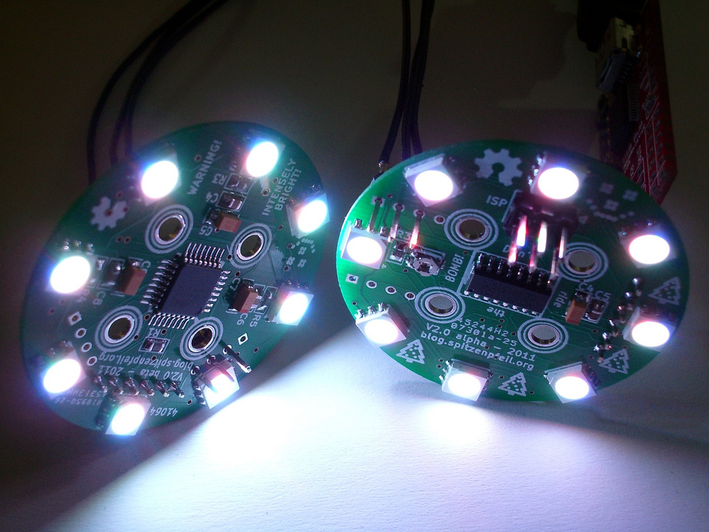
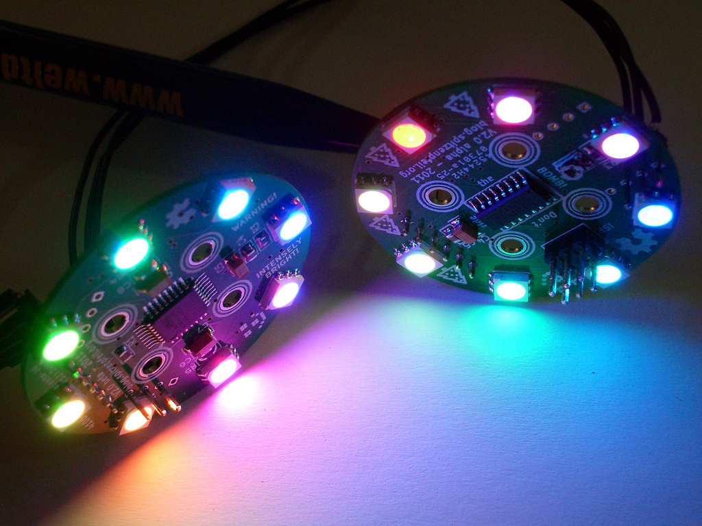
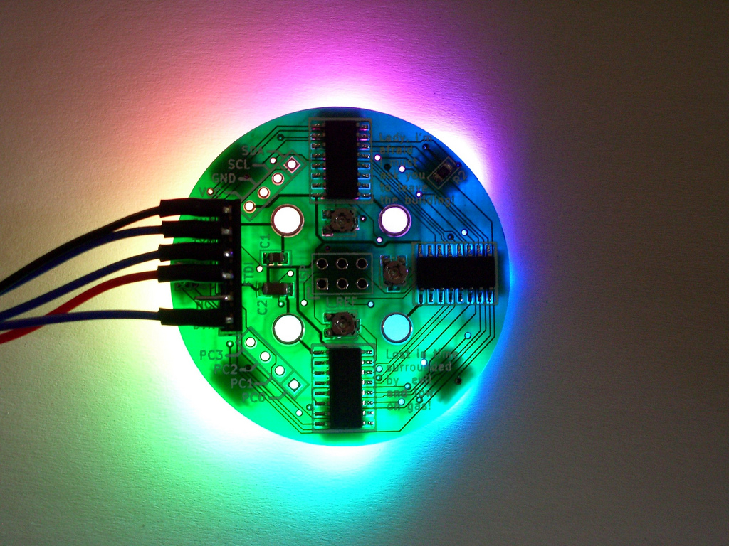
RGB LED RING V2

Files
- RGB_LED_TOY-80289ae848025eb0ddf43d037901b7deda3aad72.zip - Kicad design files for the board shown here
- rgb_led_toy_test-1f0cb8c0f35aaba925737d89bb67ba0d2534af98.zip -
Bill of Materials
| Qty | Part # | Description | Schematic ID | Source | |
|---|---|---|---|---|---|
| 1 |
|
ATMEGA168-20AU | 8BIT 16K FLASH MCU, TQFP32, 168 | Source | |
| 3 |
|
STP08CP05MTR | STP08CP05 Series 100mA 30 MHz Low Voltage Low Current Power 8-bit Shift Register | Source | |
| 3 |
|
TC33X-2-202E | TRIMMER, 2K, 3MM | Source | |
| 3 |
|
CRCW0805560RFKEA | RESISTOR, 0805, 560R , 1% | R3-5 | Source |
| 2 |
|
CRCW080510K0FKEA | RESISTOR, 0805, 10KR , 1%,0.125W | R1-2 | Source |
| 8 |
|
VAOS-5050RGB-W1 | LED, RED / GREEN / BLUE, PLCC-6 | D1-8 | Source |
| 1 |
|
929836-03-36 | Pin Strip Header | JP1 | Source |
| 5 |
|
08055C104KAT2A | CAPACITOR, 0805, 0.1UF, 50V | C1, C3, C4, C6, C8 | Source |
| 1 |
|
1206YD106KAT2A | CAPACITOR, 1206, 10UF, 16V, X5R | C2 | Source |
| 3 |
|
B45196H3106K109V17 | CAP TANT 10UF 16V 10% 1206 | C5, C7, C9 | Source |
Download BOM w/o images
Download BOM w/ images
Steps
6. Make it shine!
Assuming the board has passed close visual inspection (no shorts, no misaligned or misplaced parts...) and been cleaned with IPA, it is time to power it up and upload code. It is designed to run at 5V DC with the correct polarity. Also make sure that your USB/Serial adapter is compatible with the 6-pin connector on the board. The signal names printed on the silkscreen will be a guide. An adapter is easily built with some stranded wire and some headers.
You can easily add board-definitions to the IDE for this doodad. Simply append the contents of the 'arduino-setup' folder to the IDE's 'boards.txt' file and restart it. Once that is done, select the board, compile / upload as usual.
The I²C pins (VCC, GND, SDA, SCL) have been broken out to a separate header, so you can quite easily build a network of these boards using the 'Wire' library that comes with the IDE.
Here's a very good introductory article about how the aforementioned 'BCM' is superior to simple software driven PWM in terms of CPU utilization. Definitely worth reading.
Download steps w/o images
Download steps w/ images
Revisions
5 - Updated code/design-files + another step.
4 -
3 - Added links about BCM / BAM / MIBAM
2 -
1 - Initial project release
blog comments powered by Disqus
Back


