-
Featured User: kurt

Open-source hardware project hosting is my passion. I spend most of my free time building neat gadgets or planning what I'll build next. I love building things, and I want to make Open Hardware Hub a place that inspires others to build, ...
-
Updates 2013 February 18
It's been a while, hasn't it? Well, that's ok because we've got a lot of updates to talk about. Most of these have been effective on the site fora couple weeks now. A few may or may not be active when this article gets posted, but they'll certainly be applied in the ...
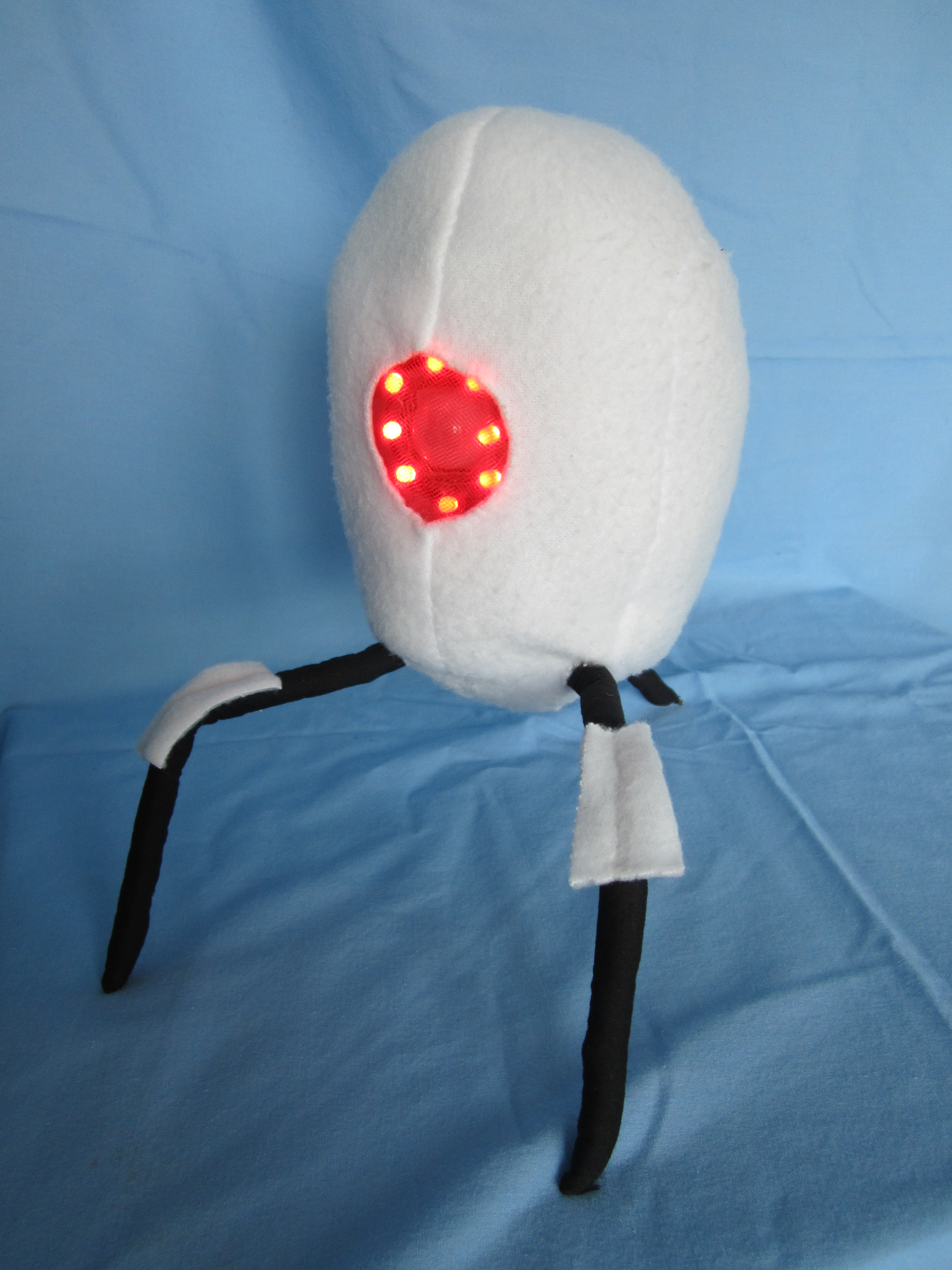
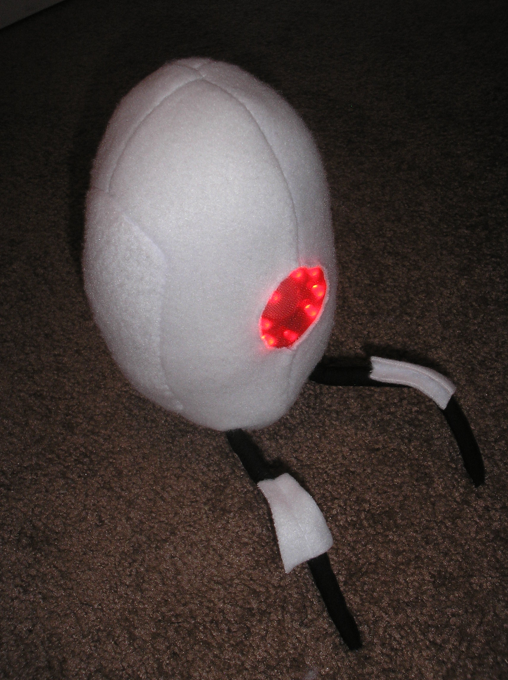
Portal Turret Plushie
Files
- Portal_Turret.pde - Portal Turret Arduino Sketch
- PIRSensorTest.pde - PIR Sensor Test Arduino Sketch
- WaveShieldTest.pde - Wave Shield Test Arduino Sketch
- test.wav - Test WAV File
- Pattern Page 1.pdf - Rear and Center Pattern
- Pattern Page 2.pdf - Front Pattern
- Pattern Page 3.pdf - Leg and Leg Cover Pattern
Bill of Materials
This open source hardware project contains no parts.
Steps
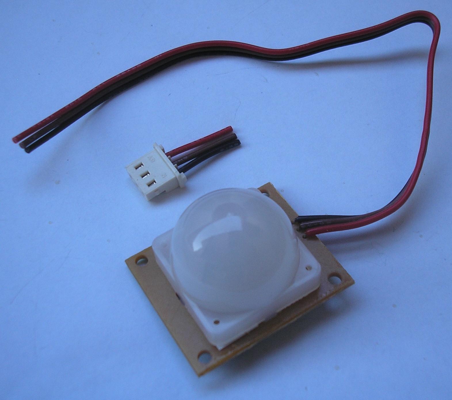
51. Prepare PIR sensor
Cut the JST connector off the PIR sensor. We'll solder these wires directly. Strip the ends of the wires so about 1/8th inch of copper is exposed.
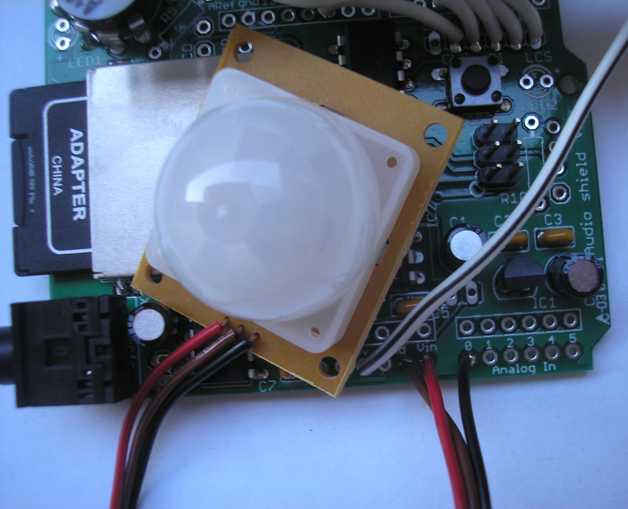
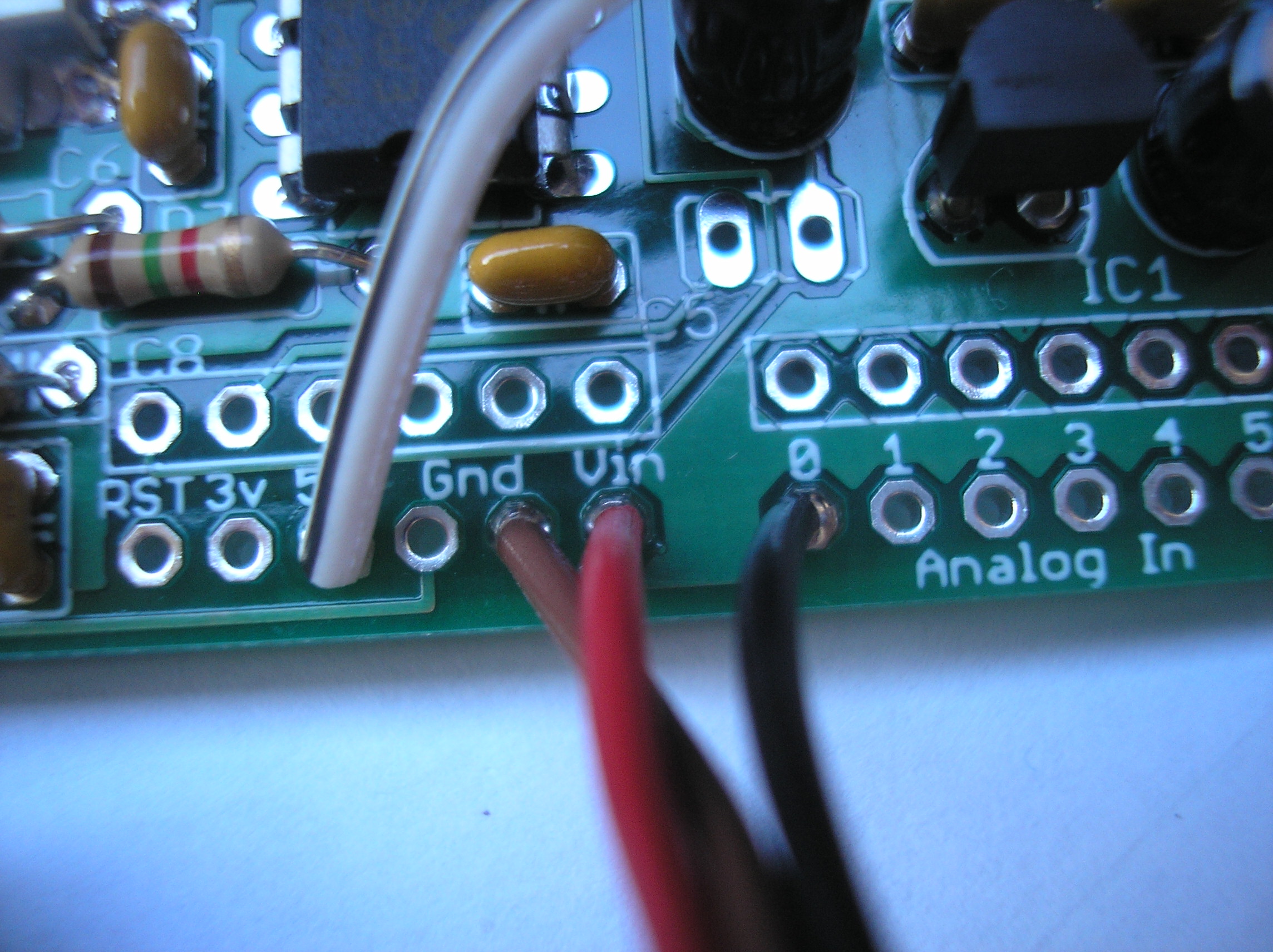
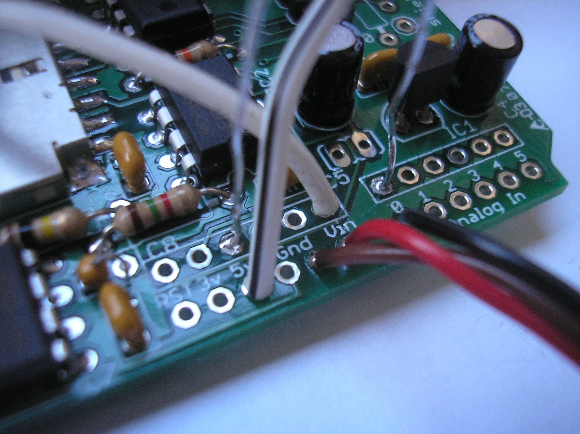
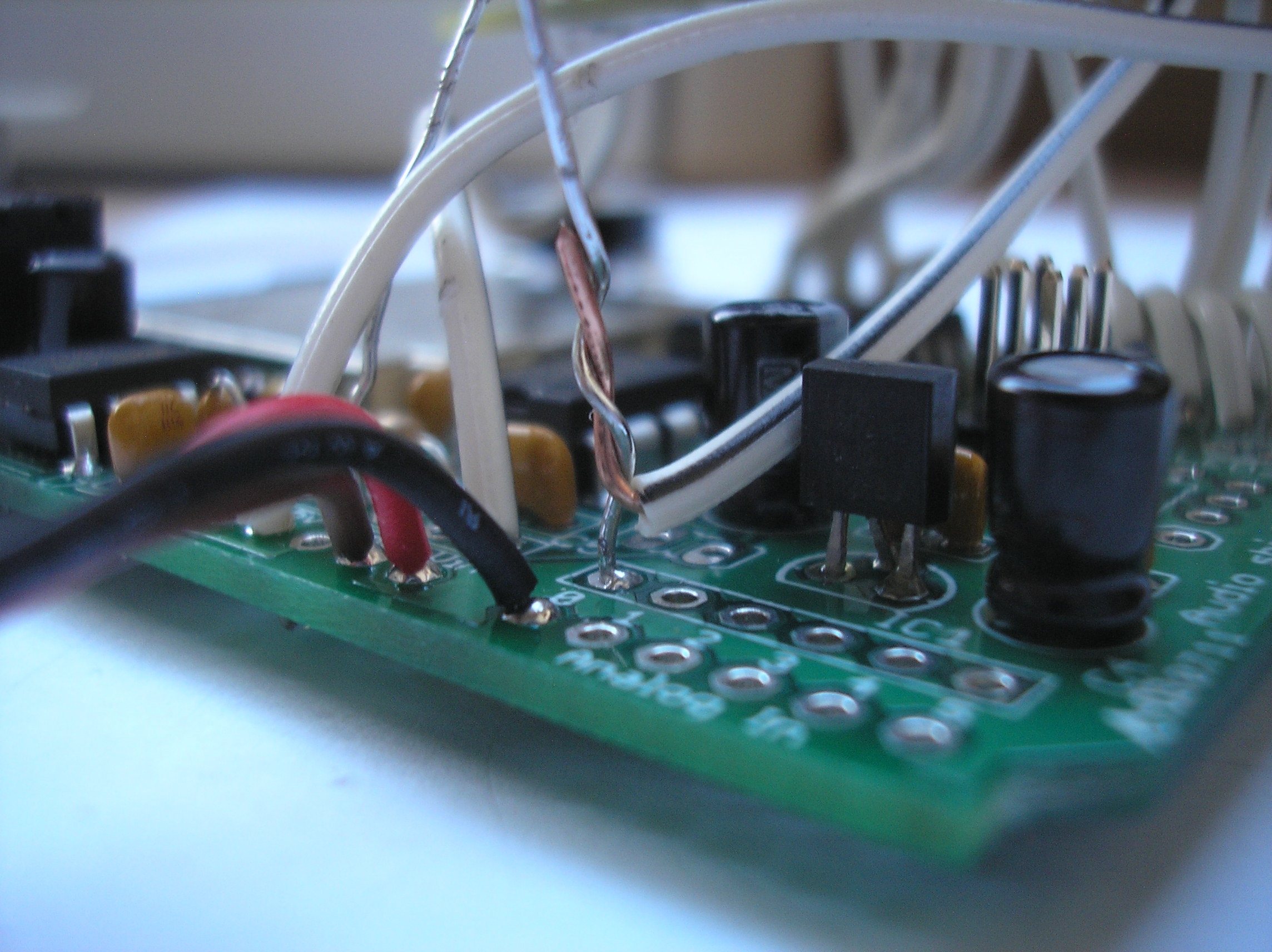
52. Solder PIR wires
Solder the PIR wires to the Wave Shield as follows: brown-->Gnd, black-->Analog In 0. DO NOT solder the red wire yet. It is not connected correctly in the picture. (Skip to step TK to see how the red wire should be connect to 5V instead of Vin.)
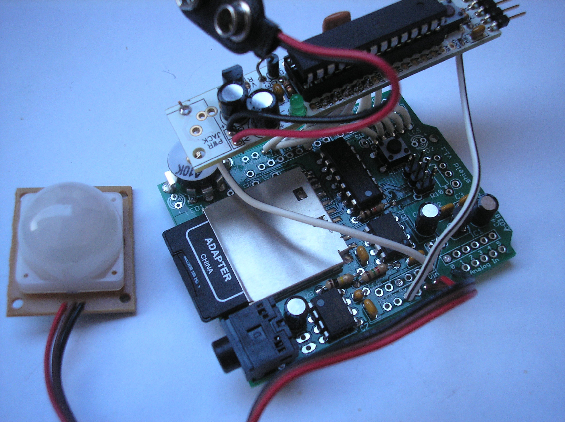
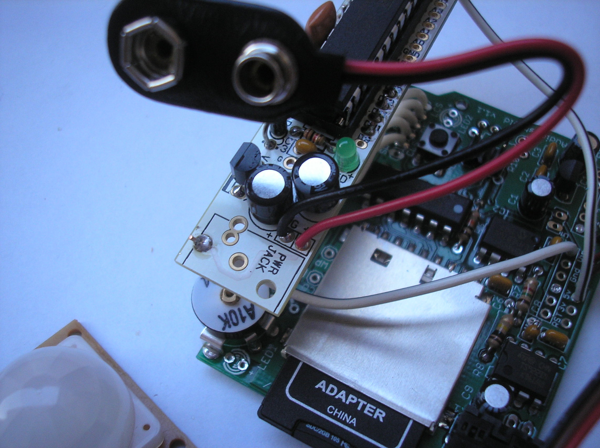
53. (Optional) Solder wire
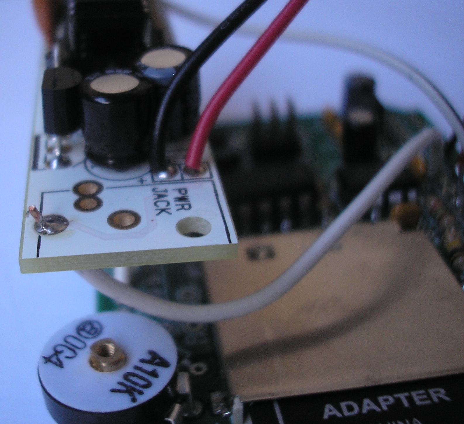
Solder a wire connecting the hole closest to the edge of the RBBB board in the PWR JACK square to Vin on the Wave Shield. This wire will supply +9V to the Wave Shield. (This step is left here to explain why this wire is present in photos of future steps.) Do not solder the 9V battery connector. Skip to step TK to see how the 9V battery clip should be connected. (In this configuration, there is no switch to turn the robot on or off.)
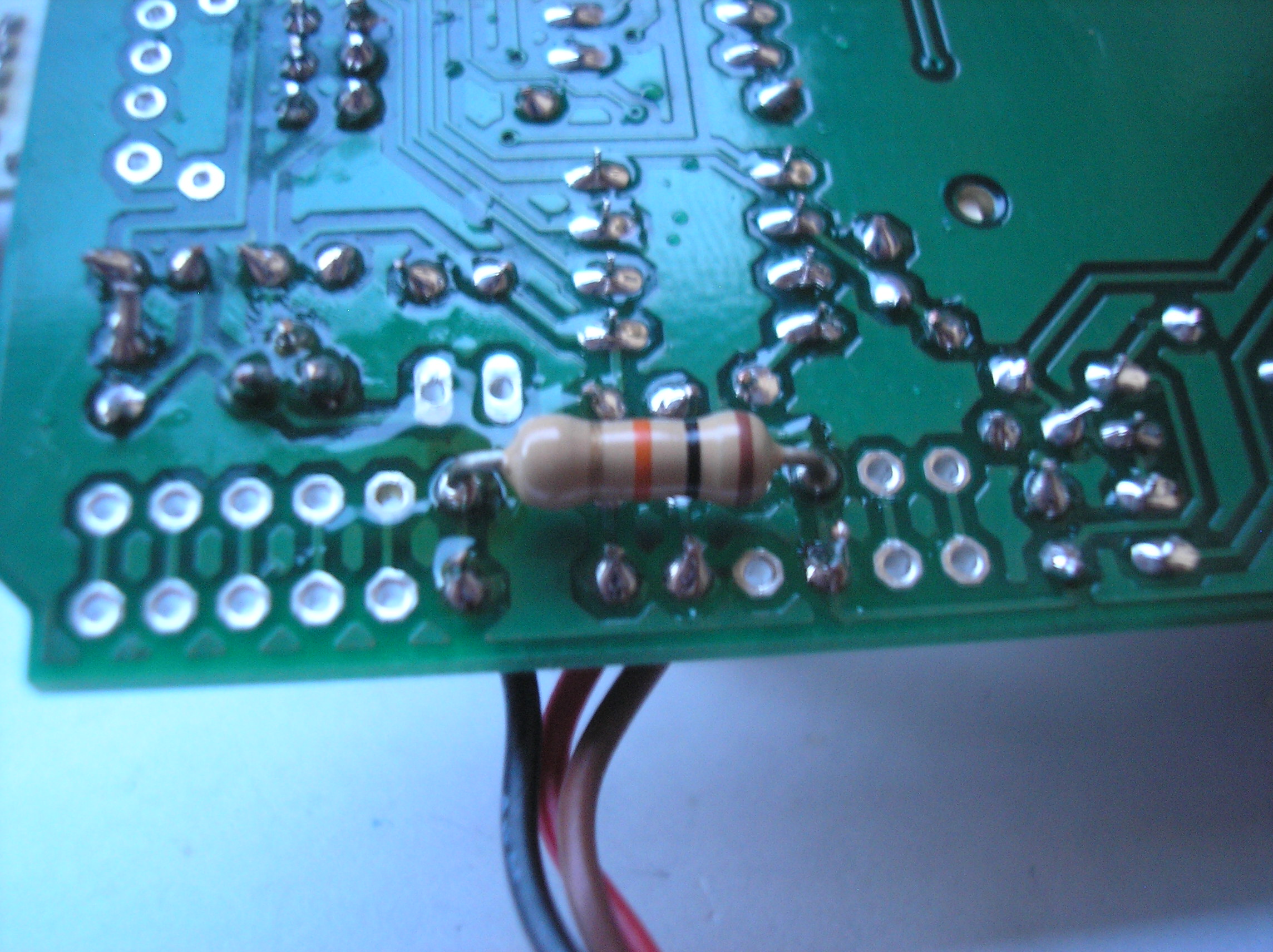
54. Solder resistor
Solder a 10k (brown-black-orange) resistor between 5V and Analog In 0 on the Wave Shield. This pull-up resistor is needed for the PIR sensor to work properly. DO NOT clip the resistor's leads. They are needed for future connections.
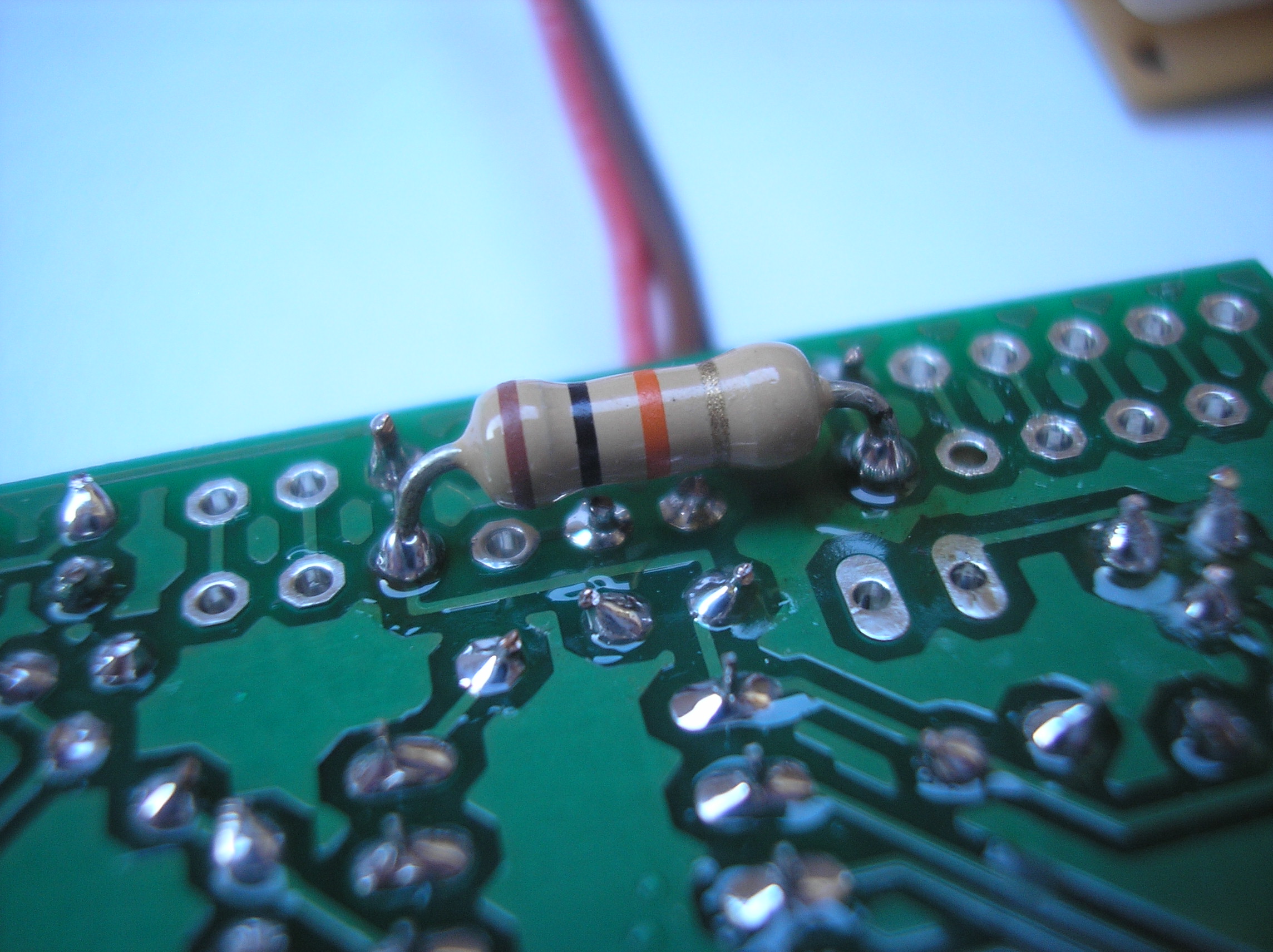
55. Wrap wire
Wrap a wire around the resistor's lead coming out of Analog In 0 on the Wave Shield. The other end of this wire goes to A0 on the RBBB.
Download steps w/o images
Download steps w/ images
Revisions
15 - added attribution note
14 - updated description
13 - added a couple switches to the parts list
12 - updated steps 52 and 53 to remove "TK" placeholders
11 - added a speaker to the BOM
10 -
9 -
8 -
7 - edited step 130
6 -
5 -
4 -
3 - updated project images.
2 - added youtube link. updated line numbers.
1 - Initial project release
Add revision
blog comments powered by Disqus
Back


