-
Featured User: kurt

Open-source hardware project hosting is my passion. I spend most of my free time building neat gadgets or planning what I'll build next. I love building things, and I want to make Open Hardware Hub a place that inspires others to build, ...
-
Updates 2013 February 18
It's been a while, hasn't it? Well, that's ok because we've got a lot of updates to talk about. Most of these have been effective on the site fora couple weeks now. A few may or may not be active when this article gets posted, but they'll certainly be applied in the ...
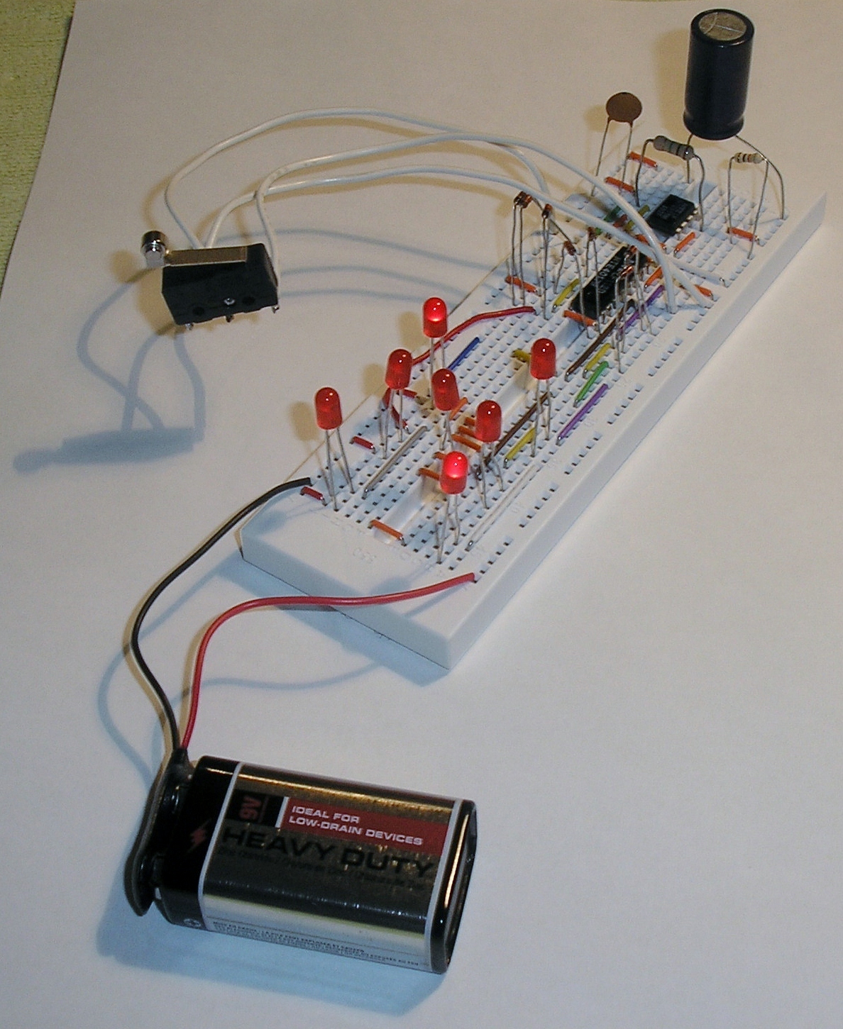
Electronic Dice
Files
- Electronic_Dice.sch - Electronic Dice EAGLE Schematic
- Electronic_Dice_Schematic.pdf - Electronic Dice PDF Schematic
Bill of Materials
| Qty | Part # | Description | Schematic ID | Source | |
|---|---|---|---|---|---|
| 1 |
|
CD4017BE | IC, 4000 CMOS, 4017, DIP16, 18V | IC2 | Source |
| 1 |
|
CF14JT1K00 | 1/4w 1K ohms 5% Carbon Film Resistors | R1 | Source |
| 1 |
|
CF14JT1M00 | 1/4w 1M ohms 5% Carbon Film Resistors | R2 | Source |
| 1 |
|
SR151A151KAR | CAPACITOR CERAMIC 150PF, 100V, C0G, RADIAL | C1 | Source |
| 7 |
|
WP7104ID | Red T-1 3 mm 40° Tinted Diffused 20 mcd 2 V Solid State LED Lamp Through Hole | LED1,LED2,LED3,LED4,LED5,LED6,LED7 | Source |
| 1 |
|
NE555P | TIMER SINGLE PRECISION,DIP8 ,0.5MHZ | IC1 | Source |
| 7 |
|
1N4001-G | DIODE RECTIFIER 1A 50V DO-41 | D1,D2,D3,D4,D5,D6,D7 | Source |
| 1 |
|
BS6I | SNAPS 9V 6" LEADS I-STYLE | JP1 | Source |
Download BOM w/o images
Download BOM w/ images
Steps


10. Insert 150pF capacitor
Insert 150pF capacitor as shown. Use a capacitor with a smaller capacitance to increase the frequency of the 555 timer and make the die "roll" through more digits while the button is held down.


11. Insert resistors
Insert 1M (brown,black,green,gold) and 1k (brown,black,red,gold) resistors as shown. Decrease the resistance of the 1M resistor to increase the frequency of the 555 timer.


Download steps w/o images
Download steps w/ images
Revisions
6 - updated description
5 - updated step numbers.
4 - changed LED part
3 - added a description for the project image
2 - added file descriptions
1 - Initial project release
blog comments powered by Disqus
Back


