-
Featured User: kurt
Open-source hardware project hosting is my passion. I spend most of my free time building neat gadgets or planning what I'll build next. I love building things, and I want to make Open Hardware Hub a place that inspires others to build, ...
-
Updates 2013 February 18
It's been a while, hasn't it? Well, that's ok because we've got a lot of updates to talk about. Most of these have been effective on the site fora couple weeks now. A few may or may not be active when this article gets posted, but they'll certainly be applied in the ...
Arduino Hardware Reset Circuit Breadboard
By: kurt
This circuit uses one pin to let you reset your Arduino in code. It pulls reset low for a couple milliseconds to ensure the Arduino has enough time to complete its reset cycle.
Download project description w/o images
Download project description w/ images
Files
- ArduinoReset.sch - Arduino Reset EAGLE Schematic
- ArduinoReset.brd - Arduino Reset EAGLE Board
- Arduino Reset.zip - Arduino Reset Gerber
- Arduino_Reset.pde - Arduino Reset Example Sketch
Bill of Materials
| Qty | Part # | Description | Schematic ID | Source | |
|---|---|---|---|---|---|
| 1 |
|
NE555P | TIMER SINGLE PRECISION,DIP8 ,0.5MHZ | IC1 | Source |
| 1 |
|
CF14JT100R | 1/4w 100 ohms 5% Carbon Film Resistors | R4 | Source |
| 1 |
|
CF14JT1K00 | 1/4w 1K ohms 5% Carbon Film Resistors | R3 | Source |
| 1 |
|
CF14JT10K0 | 1/4w 10K ohms 5% Carbon Film Resistors | R2 | Source |
| 1 |
|
CF14JT100K | AXIAL CARBON FILM RES 1/4W 100K OHMS 5% LF | R1 | Source |
| 1 |
|
EEA-GA1HR10 | CAP ALUM 0.1UF 50V 20% RADIAL | C1 | Source |
| 1 |
|
SR215C103KAR | CAPACITOR, 0.01UF, 50V | C2 | Source |
| 1 |
|
2N3904BU | TRANSISTOR, NPN 200MA TO-92 | Q1 | Source |
Download BOM w/o images
Download BOM w/ images
Steps
11. Insert current-limiting resistor R4
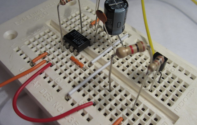
Put a 100 ohm resistor between the emitter of the transistor and ground. This resistor limits the current that is sourced from the Arduino's reset pin. If the current got too high it could damage either the Arduino or the transistor Q1.
12. Insert base resistor R3
Insert a 1k ohm resistor between the base of the transistor and pin 3 of the IC. This resistor limits the current flowing into the base of transistor Q1. Transistors only need a small amount of current to turn on, so we limit the base current to less than 5mA with this resistor.
13. Connect input signal
Pin 3 of the IC is the input of the circuit. The input should normally be held high. When you want to do a hardware reset of the Arduino, pull this pin low in your code. You can use any of the Arduino's analog or digital outputs for this.
14. Connect output reset signal
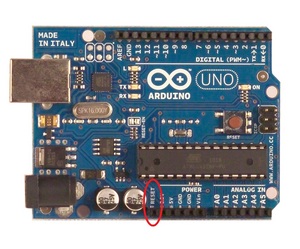
Connect the collector of the transistor to the pin marked RESET on the Arduino.

15. Completed hardware
Now the hardware is finished, and you need to program your Arduino to use this reset circuit. The code needed for this circuit is very simple.
Download steps w/o images
Download steps w/ images
Revisions
7 - fixed steps 3 and 4
6 - fixed an error in the description
5 - fixed the text for the third step
4 - none
3 - changed name to indicate this project is built on a breadboard
2 - updated description
1 - Initial project release
Add revision
blog comments powered by Disqus
Back


